FLOWSIC600 · Operating Instructions · 8010458 V 2.0 · © SICK MAIHAK GmbH 85
Appendix
● Any flow rates given above are also valid in the bidirectional mode.
● G-classes marked with an asterisk (*) must only be used in configuration No. 2 (see
→
pg.27, 3.2.2).
● G-classes marked with an (E) have an extended max. flow rate (max. flow velocity v
max
=
36 m/s) related to commonly established turbine meter G-classes
● The transition flow Q
t
is based on the flow range the meter is designed for according to
the main plate. It is:
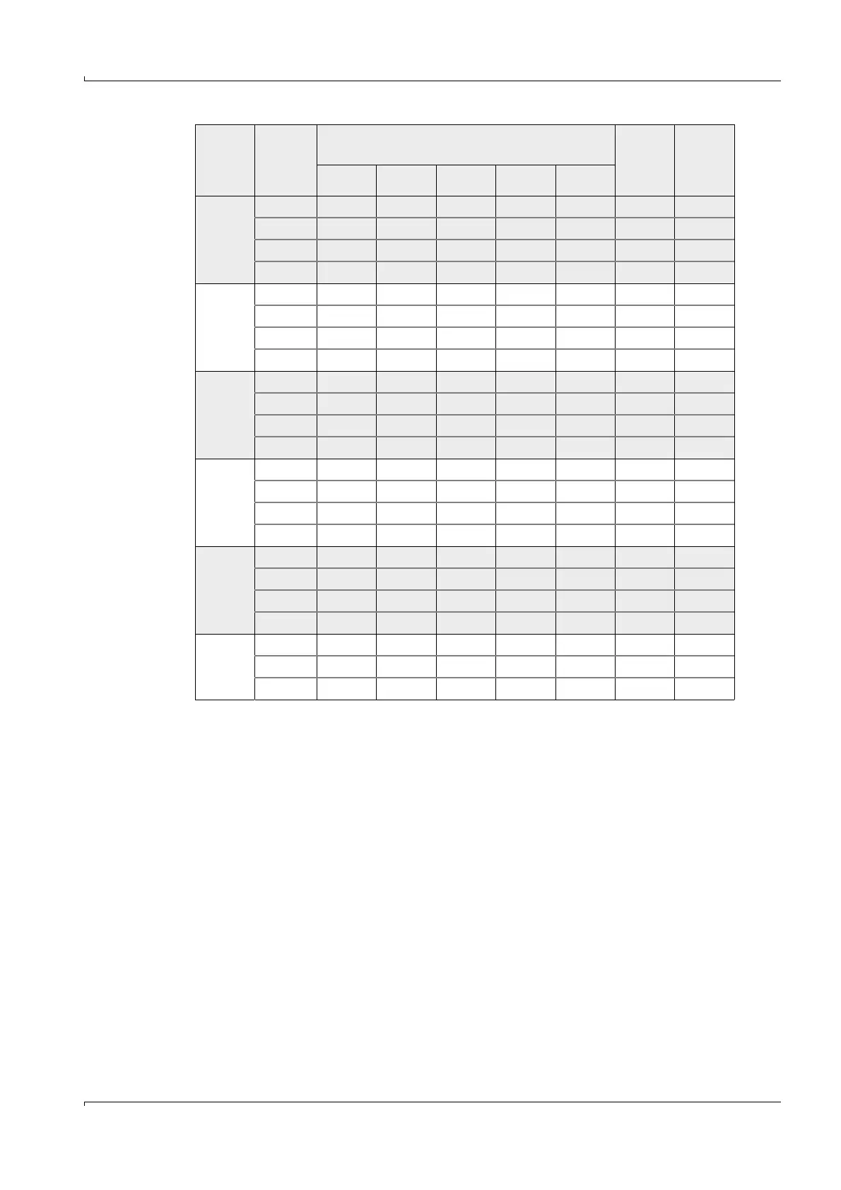
DN 500
(20“)
G4000 200 320 6500 1110
G6500 200 320 500 10000 720
G10000 200 320 500 800 16000 450
G10000 E 200 20000 360
DN 600
(24“)
G6500 320 500 10000 720
G10000 320 500 800 16000 450
G16000 320 500 800 1300 25000 288
G16000 E 320 32000 225
DN 700
(28“)
G6500 500 10000 720
G10000 500 16000 450
G16000 500 25000 290
G25000 400 500 40000 180
DN 800
(32“)
G10000 500 16000 450
G16000 500 25000 290
G25000 500 40000 180
G25000 E 500 48000 150
DN 900
(36“)
G10000 800 16000 450
G16000 800 25000 290
G25000 800 40000 180
G40000 650 800 65000 111
DN 1000
(40“)
G16000 1300 25000 290
G25000 1300 40000 180
G40000 800 1300 65000 111
- for a flow range of 1:20 Qt=0.20 Q
max
and
- for a flow range of 1:30 Qt=0.15 Q
max
and
- for a flow range of
≥
1:50 Qt=0.10 Q
max
.
Meter
size
G-class
Measuring range (Qmin [m³/h])
Max. flow
rate
Qmax
[m³/h]
Meter
factor
[pulses/
m³]
1:100 1:80 1:50 1:30 1:20