12
8012704/YHS4/V2-0/2016-10 | SICKOPERATING INSTRUCTIONS | GM32
Subject to change without notice
2 PRODUCT DESCRIPTION
2.5 GM32 design
The GM32 Cross-Duct version consists of:
● Sender/receiver unit (SR-unit)
The SR-unit contains optical and electronic subassemblies.
The concentration calculation of the sample gas is performed in the SR-unit according to
the absorption spectroscope principle.
● Reflector unit
The reflector unit reflects the measuring beam back to the SR-unit.
Different versions exist for the “flange - flange” distances from a total of 0.4 ... 12 m, see
“Example: Installation option”, page 15 and see “Installing the “flanges with tube” on the
gas duct”, page 16.
● 2 purge air fixtures
The purge air fixtures contain sockets to connect purge air hoses as well as connections
for external sensors (filter monitor of purge air unit, temperature sensor).
● 2 “flanges with tube”
The “flanges with tube” are mounted on the gas duct and include the flanges to install
the purge air fixtures.
ANSI or DIN flanges can be used alternatively to the flanges supplied.
● For flange DN125: Two purge air units.
For flange DN100: One purge air unit and two air hoses to the SR and reflector unit.
● Connection unit, see “Installing the connection unit”, page 18 and “Connection dia-
gram”, page19.
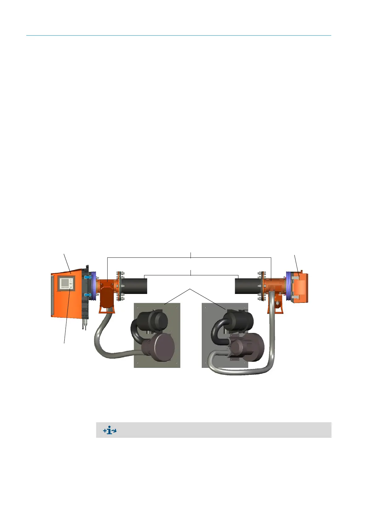
Fig. 2: GM32 Cross Duct with 2 purge air units
The purge air unit supplies filtered ambient air to the purge air fixtures and protects the
windows of the SR-unit and the reflector from contamination and high gas temperatures.
The SR-unit and the reflector unit each have their own purge air unit.
The purge air is blown into the gas duct through the flange with tube.
SR-unit Reflector unit
Purge air unit
Operator panel
(For the “Pro” variant)
“Flanges with tube”
Purge air fixtures
Further information on the purge air unit → Operating Instructions of the purge air unit.