19
8012704/YHS4/V2-0/2016-10 | SICK OPERATING INSTRUCTIONS | GM32
Subject to change without notice
PREPARING THE GAS DUCT SIDE 3
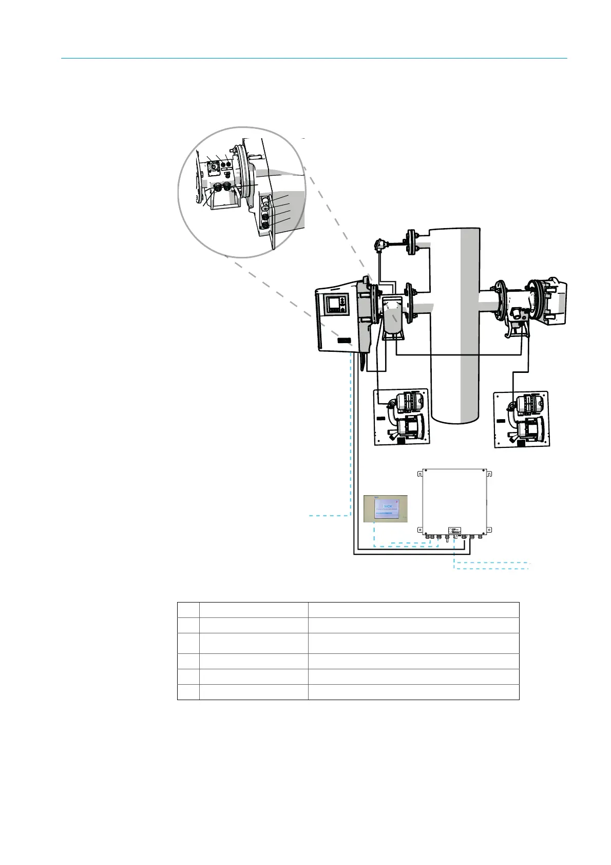
3.5 Laying the electrical connection lines
Fig. 9: Connection diagram
4
7
6
5
1
3
2
Sender/receiver unit (SR)
Reflector (Ref)
Pressure and temperature
sensor
Purge air unit SLV4 Wiring and technical data, see Data Sheet SLV4
Connection unit (AU)
SCU (option)
Table 3: Hardware connection diagram