20
8012704/YHS4/V2-0/2016-10 | SICKOPERATING INSTRUCTIONS | GM32
Subject to change without notice
3 PREPARING THE GAS DUCT SIDE
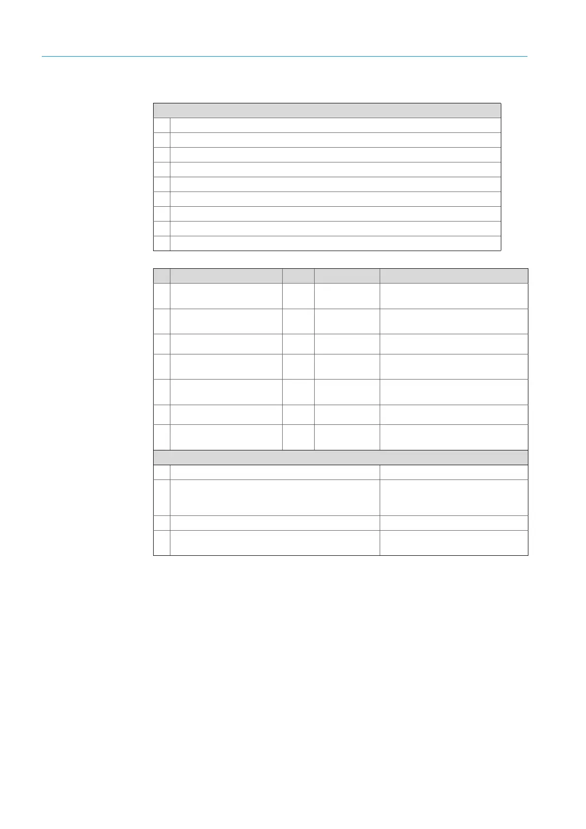
Connections of sender/receiver unit and purge air fixture (see detailed view)
Purge air supply connection
Temperature sensor connection
Purge air/filter monitor connection
CAN line connection: Purge air fixture- reflector (see á)
CAN line connection: Purge air fixture - SR-unit (see â)
Ethernet PC/network connection
Power supply connection
CAN line connection: (see å)
Purge air fixture connection
Table 4: Purge air fixture for sender/receiver unit and purge air fixture
Signal line for connection Length Part number Remark
Purge air fixture - pressure
sensor
à
Purge air fixture - tempera-
ture sensor
á SR – reflector (CAN line)
● 12 m
● 24 m
● 2020861
● 2027031
Order separately
â
SR – purge air fixture
(CAN line)
0.8 m 2023704 Included in the purge air fixture (SR)
ã
Filter monitor 5 m 2032143
Included in the respective purge air fix-
ture (SR + Ref)
ä Power supply SR (standard)
● 10 m
● 20 m
● 2046548
● 2046549
å
CAN line connection unit -
sender/receiver unit
● 10 m
● 20 m
● 2028786
● 2045422
Order separately
On-site lines
a Ethernet – PC/network line
bSCU connection
On-site
Configuration and connections
see “Operating Instructions SCU”
c Power supply 100 ... 240 V AC, 50/60 Hz On-site
d On-site terminal connections (inputs/outputs)
Technical Information “Modular
System I/O”
Table 5: Signal lines