21
8012704/YHS4/V2-0/2016-10 | SICK OPERATING INSTRUCTIONS | GM32
Subject to change without notice
PREPARING THE GAS DUCT SIDE 3
3.5.1 General information
3.5.2 Connecting I/O interfaces (option)
▸ Route the data lines through the M screw fittings.
▸ Connect the data line.
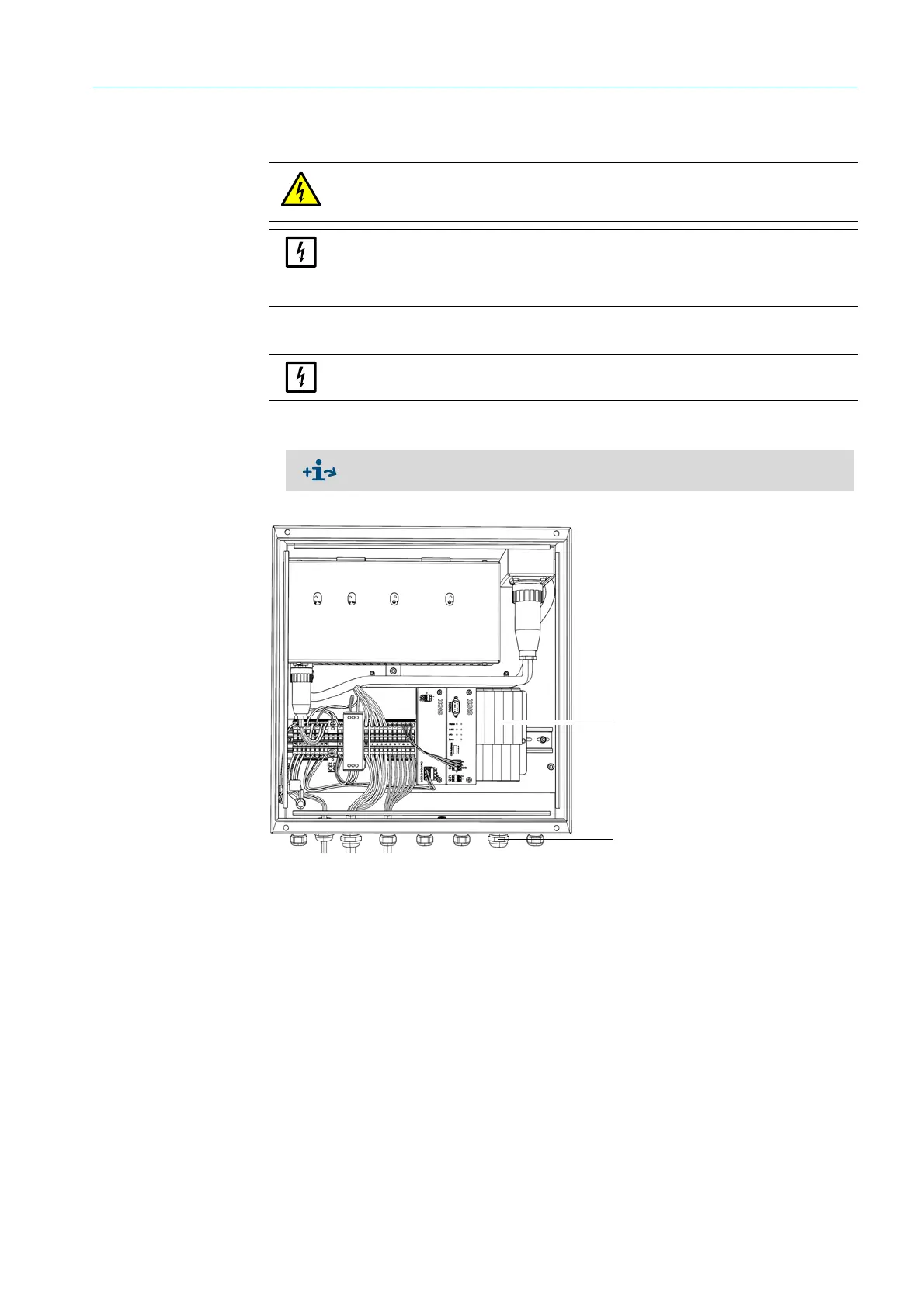
Fig. 10: Connection unit (inside): Location of I/O modules
CAUTION: Hazard caused by electric voltages
▸ Only let the work described in the following be carried out by skilled electricians famil-
iar with potential hazards.
NOTE:
Before signal connections are established (also with plug connections):
▸ Disconnect the GM32 and any connected devices from the voltage supply.
Otherwise the internal electronics can be damaged.
!▸
Do not lay power supply cables immediately next to signal cables.
▸ Description of I/O modules
→ Operating Instructions “Modular I/O System”.
I/O module
M screw fittings