15
8012704/YHS4/V2-0/2016-10 | SICK OPERATING INSTRUCTIONS | GM32
Subject to change without notice
PREPARING THE GAS DUCT SIDE 3
3.2 Overview of the installation steps (duct-side work)
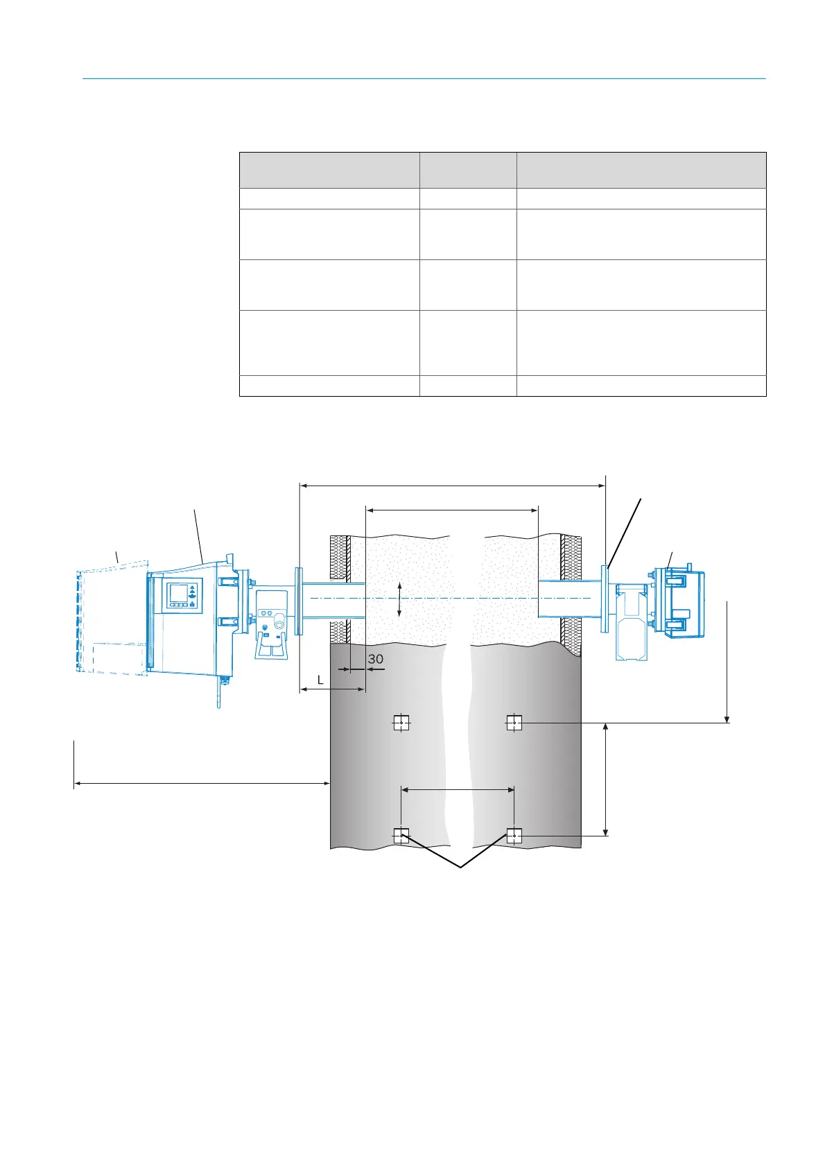
Fig. 4: Example: Installation option
Special tools / auxiliary materi-
als
Part number Required for
Adjustment device 2034121 Alignment of “flanges with tube”
Jaw wrench
19 mm
24 mm
--- Flange screw fitting
Screwdriver for
0.6 x 3.5 mm
1.0 x 5.5 mm
--- Connections
Allen key
3 mm
4 mm
5 mm
--- Connections
Personal protective equipment --- Protection when working on the stack
Table 2: Special tools /auxiliary materials required for installation
Space requirement to
open the SR-unit
Mounting flange:
L = 240 mm (standard)
Attachment (e.g., 4 steel pipes, 50 x 5 mm) for purge air unit
(Shown for 1 unit)
SR-unit
Approx. 1.5 m
Min. 700 mm
Reflector unit
Flange – flange distance
Active measuring path
Deviation of optical
axis: Max. 1°: