42
8012704/YHS4/V2-0/2016-10 | SICKOPERATING INSTRUCTIONS | GM32
Subject to change without notice
5 OPERATION
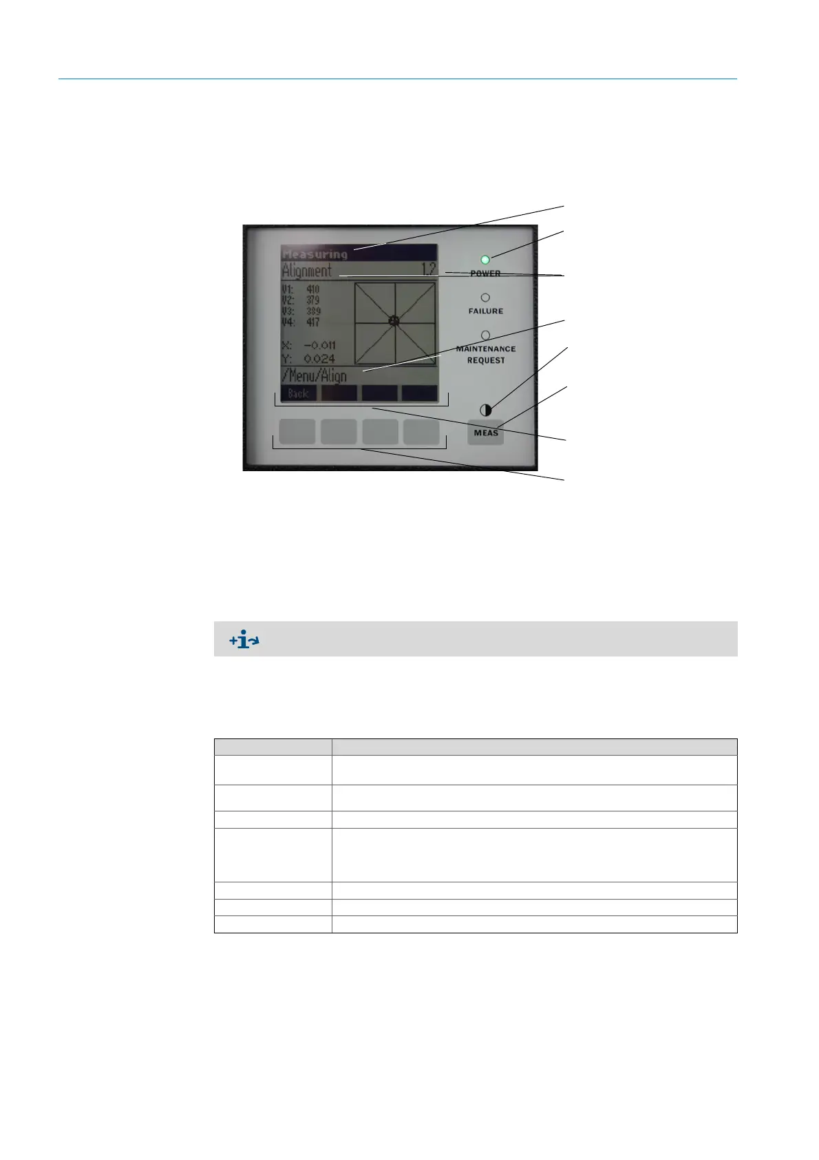
5.2 Operator panel
The operator panel is located on the right side of the SR-unit housing.
Fig. 29: Significance of display
5.2.1 Status indicators (LEDs)
Significance of LEDs
● Green LED on: Power supply is in order.
● Yellow LED on: Maintenance request.
● Red LED on: Malfunction.
5.2.2 Button assignment
Button assignment depends on the menu selected and is shown above the respective but-
ton.
5.2.3 Contrast setting
1 Press the MEAS button for more than 3 seconds.
2 Set the desired contrast level with both middle buttons and .
Operating state
Status indicators (LEDs)
see “Diagnosis”, page 44
Current menu with
menu level (numeric display)
Menu level
Contrast setting
see “Contrast setting”
MEAS button
see “Button assignment”
Significance of button
(menu dependent)
see “Button assignment”
Buttons
Further information on LED significance, see “Diagnosis”, page 44
Button assignment Significance
MEAS Returns to the display of the measured value screen from any menu
All inputs that have not been terminated with
Save
are discarded
If the
MEAS
button is depressed for more than 3 seconds: The contrast setting is displayed
Menu Opens the main menu (menu tree)
Diag
Diag
is shown only when there is a message.
Press this button to show message.
More information on diagnosis,
see “Diagnosis”, page 44
List of error messages,
see “Error messages”, page56
Enter Opens the selected menu level
Save Saves changed parameters
Start Starts the displayed action