67
8012704/YHS4/V2-0/2016-10 | SICK OPERATING INSTRUCTIONS | GM32
Subject to change without notice
TECHNICAL DATA 9
9.2.6 Characteristic data for electric isolation
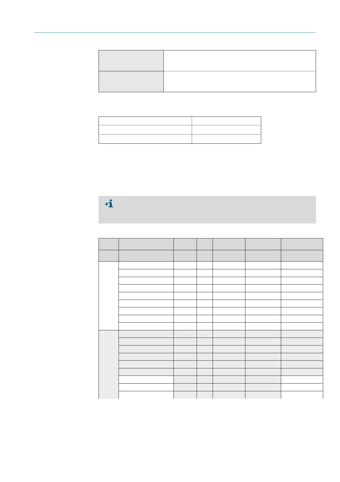
9.3 Modbus Register Mapping
9.3.1 Mapping of GM32 measuring components
● Modbus register for 16 components
Digital inputs
4 inputs
● 3.9 V, 4.5 mA, 0.55 W
● Per module, modules can be selected and extended as required.
Bus protocol
● OPC via external server
● TCP/IP via Ethernet
● Modbus TCP
Relay contact <-> PE 860 V AC
Relay contact <-> relay contact
860 V AC
Relay contact <-> actuation
1376 V AC
Table 24: Technical data connection unit
● Address, address start and address end of further components (component 4, com-
ponent 5, ...) are each incremented with 17, the sequence of the items remains the
same.
● The sequence of the components depends on the GM32 configuration.
Name Item Address Data type Register type Comment
Start Width
Measured Value 5000 2 32 Bit float Input register Measuring value
Status 5002 1 16 Bit integer Input register Status
0)
Zero Point Value 5003 2 32 Bit float Input register Zero point
Span Point Value 5005 2 32 Bit float Input register Span point
Start of measuring range 5007 2 32 Bit float Input register min of range
End of measuring range 5009 2 32 Bit float Input register max of range
Regression coefficient C0 5011 2 32 Bit float Input register Offset
Regression coefficient C1 5013 2 32 Bit float Input register Slope
Regression coefficient C2 5015 2 32 Bit float Input register Correction factor
Measured Value 5017 2 32 Bit float Input register Measuring value
Status 5019 1 16 Bit integer Input register Status
0)
Zero Point Value 5020 2 32 Bit float Input register Zero point
Span Point Value 5022 2 32 Bit float Input register Span point
Start of measuring range 5024 2 32 Bit float Input register min of range
End of measuring range 5026 2 32 Bit float Input register max of range
Regression coefficient C0
5028 2 32 Bit float Input register Offset
Regression coefficient C1
5030 2 32 Bit float Input register Slope
Regression coefficient C2
5032 2 32 Bit float Input register Correction factor
Table 25: Modbus component register (for the first 3 components)