28
8012704/YHS4/V2-0/2016-10 | SICKOPERATING INSTRUCTIONS | GM32
Subject to change without notice
4 START-UP
4.2 Overview of assembly steps
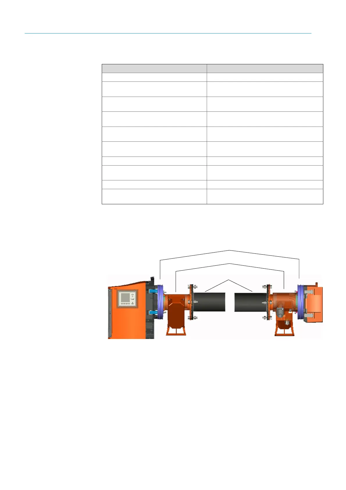
4.3 Installation drawing
Fig. 13: Installation drawing
Procedure Reference
Removing the transport safety devices see “Transport safety devices”, page 29
Installing the purge air fixtures on the flange
with tube
see “Installing the purge air fixtures on the flange
with tube”, page 30
Installing the device flange on the purge air fix-
ture
see “Installing the device flange on the purge air fix-
ture”, page 31
Aligning the device flanges and purge air fix-
tures
see “Aligning the device flanges and purge air fix-
tures”, page 32
Electrical connection of the SR-unit and reflec-
tor unit
see “Electrical connection of the SR-unit and reflec-
tor unit”, page 34
Switching on the power supply
see “Switching on the power supply of the GM32”,
page 34
Start-up of the purge air supply see “Start-up of the purge air supply”, page 35
Installing the SR-unit and reflector unit on the
device flange
see “Installing the SR-unit and reflector unit on the
device flange”, page 36
Optical fine alignment of the SR-unit see “Optical fine alignment of the SR-unit”, page 36
Installing weatherproof covers (option)
see “Installing weatherproof covers (option)”, page
39
Table 6: Installation steps overview
SR-unit
Flange with tube
Purge air fixture
Reflector unit
Device flange