34
8012704/YHS4/V2-0/2016-10 | SICKOPERATING INSTRUCTIONS | GM32
Subject to change without notice
4 START-UP
4.8 Electrical connection of the SR-unit and reflector unit
1 Connect the electric lines of the connection unit to the SR-unit and reflector unit.
2 Connect the electric line from the purge air fixture of the SR-unit to the purge air fixture
of the reflector unit.
3 Connect the electric line from the purge air unit to the purge air fixture (terminal: SLV fil-
ter).
4 Screw the grounding conductor (2.5 mm
2
) of the equipment ground tight to the screw
terminal, see Fig. 21.
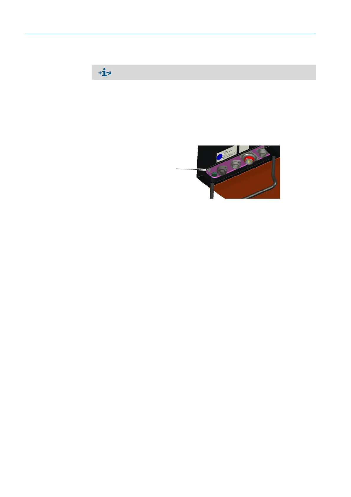
Fig. 21: Connection of the grounding conductor at the bottom of the SR-unit
4.9 Switching on the power supply of the GM32
1 Switch on the power supply on the fuse, fitted by the operator, of the connection unit.
2 An initialization screen is shown on the operator panel of the sender/receiver unit (for
the “Pro” variant).
3 Measured values are then shown.
Ignore the displays until the start-up of the GM32 is complete.
Connection diagram, see “Laying the electrical connection lines”, page 19.
Connection
grounding conductor