33
8012704/YHS4/V2-0/2016-10 | SICK OPERATING INSTRUCTIONS | GM32
Subject to change without notice
START-UP 4
3 On the side of the reflector unit:
Remove the protective cap from the adjustment tube.
Insert the adjustment device with tube into the device flange and attach with the quick-
release fasteners.
Note: Both pins of the device flange must fit into the respective drilled holes of the
adjustment device.
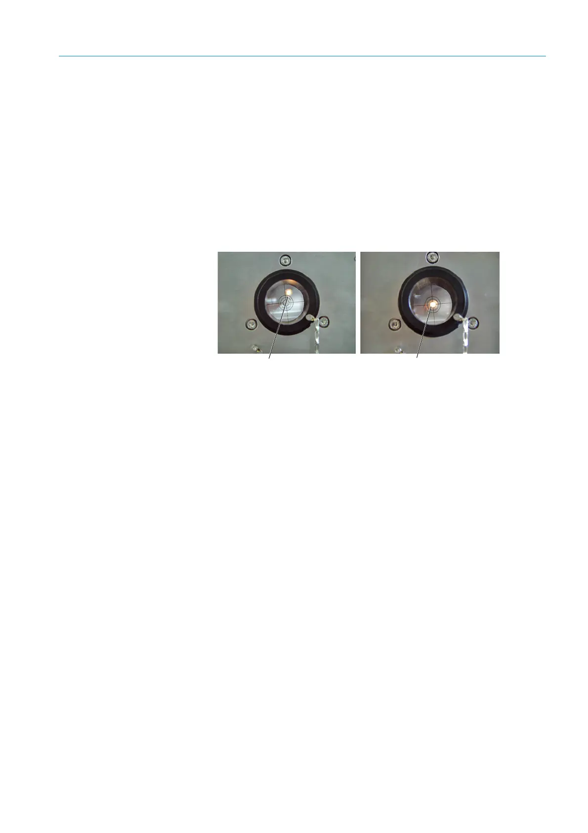
4 Align the device flange which contains the adjustment tube with the screws for the hori-
zontal and vertical adjustment, see Fig. 19: The light spot must be shown centrally in the
target of the adjustment tube, see Fig. 20.
If centering is not possible: Unscrew the device flanges from the flange with tube and
check the optical alignment of the flange with tube, see “Installing the “flanges with
tube” on the gas duct”, page 16.
Fig. 20: Optical alignment on the window of the adjustment tube
5
Interchange the adjustment device with light source and the adjustment tube.
Align the flange which contains the adjustment tube again: The light spot must be shown
centrally in the target of the adjustment tube.
6 Remove the adjustment device again.
7 Switch the LED on (for GM32 LN version).
Not aligned correctly
Aligned correctly