51
8012704/YHS4/V2-0/2016-10 | SICK OPERATING INSTRUCTIONS | GM32
Subject to change without notice
MAINTENANCE 6
6.7 Replacing the sender lamp and LED GM32LN
6.7.1 Tools required
6.7.2 Sender lamp with LED unit
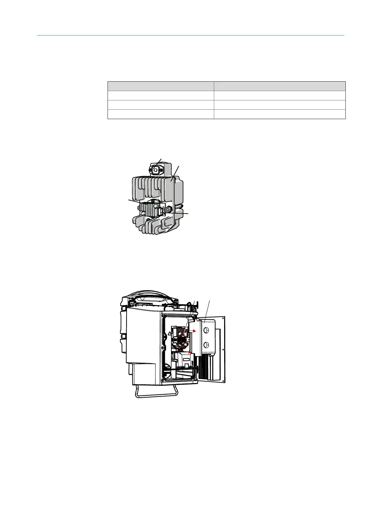
Fig. 37: Description of sender lamp with LED unit
Removing the sender lamp with LED unit
1 Switch the GM32 off using the fuse fitted by the operator.
2 Loosen 5 screws on the rear side of the SR-unit and swivel the rear side out.
3 Pull off the lamp cover.
Fig. 38: Lamp cover
4
Pull off the voltage supply line of the LED.
5 Loosen screw (crosshead) of the plug of the sender lamp voltage supply and disconnect
the plug.
Tools Required for
Phillips screwdriver (0.5 x 3.0M) Connect voltage supply line of sender lamp.
Allen (5 M) Retaining screws of UV lamp
Allen (2,5 M) Retaining screws of LED unit
Table 12: Tools required for exchange of lamps
Sender lamp LN
LED unit
Connection of LED unit power supply
Connection of sender lamp power supply