46
8012704/YHS4/V2-0/2016-10 | SICKOPERATING INSTRUCTIONS | GM32
Subject to change without notice
5 OPERATION
5.2.5.4 Adjustments
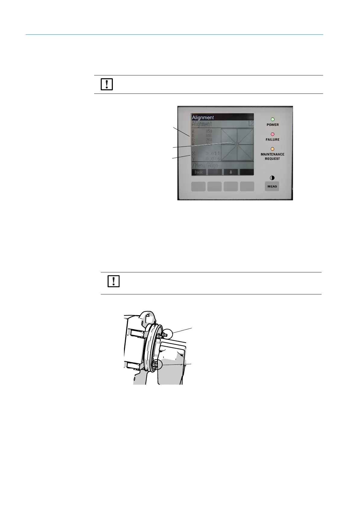
Alignment adjust (manual optical alignment)
Fig. 31: Manual alignment of optical axis
1 Press the “Start” button: The GM32 switches to a defined state.
A crosshair with a focal point and X/Y values are shown on the screen.
2 Tolerances:
X: –0.05 ... +0.05
Y: –0.05 ... +0.05.
The focal point is then in the center of the crosshair.
Adjustment:
Adjust the optical alignment by turning both adjustment screws on the device flange of
the SR-unit (19 mm wrench).
Fig. 32: Alignment on the device flange
– Horizontal adjustment causes a horizontal adjustment of the focus.
– Vertical adjustment causes a vertical adjustment of the focus.
3 The values for the light energy V1 .. V4 must be in the range 250 ... 500 and approxi-
mately have the same size.
▸ Perform this work only when the SR-unit is at operating temperature (in operation for
at least 30 minutes).
Light energy
Focal point
Value X
Value Y
The display on the monitor reacts to the adjustment with a delay.
▸ Perform adjustments slowly and wait for approx. 20 seconds until the display on
the monitor has been updated.
Horizontal adjustment
Vertical adjustment