22
8012704/YHS4/V2-0/2016-10 | SICKOPERATING INSTRUCTIONS | GM32
Subject to change without notice
3 PREPARING THE GAS DUCT SIDE
3.5.2.1 Default values for interfaces
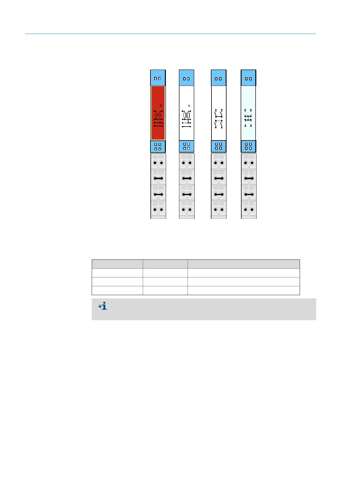
Fig. 11: Example: I/O module pin assignment
State
Analog
Output
0 ...20mA
Load
500
AO1 AO2
- -
12
Shield
State
Analog
Input
0...20mA
Sense
100
AI1 AI2
- -
1
2
Shield
State
Digital
Output
Signal
Relais
DO1
DO3
State
Digital
Input
DI1 DI2
DI3 DI4
12
43
DO4
DO2
12
4
3
23
22
21
13
12
2414
22
13
2414
11
11
11
21
21
21
11
12
12
12
23
23
23
22
22
13
13
14
14
24
24
11-12 = AO1
21-23 = AO2
11-12 = AI1
21-23 = AI2
11-12 = DO1
21-22 = DO2
13-14 = DO3
23-24 = DO4
11-12 = DI11
21-22 = DI2
13-14 = DI3
23-24 = DI4
Analog input Pin assignment Function
AI 1 11, 12 Temperature (internally wired)
AI 2 21, 23 Pressure (internally wired)
AI 3 11, 12 Humidity
The analog input assignment shown in the Table is a default setting. The assignment of
the inputs can be freely configured with SOPAS. For more information, see the SOPAS ET
Operating Instructions.