18
8012704/YHS4/V2-0/2016-10 | SICKOPERATING INSTRUCTIONS | GM32
Subject to change without notice
3 PREPARING THE GAS DUCT SIDE
3.3 Installing the connection unit
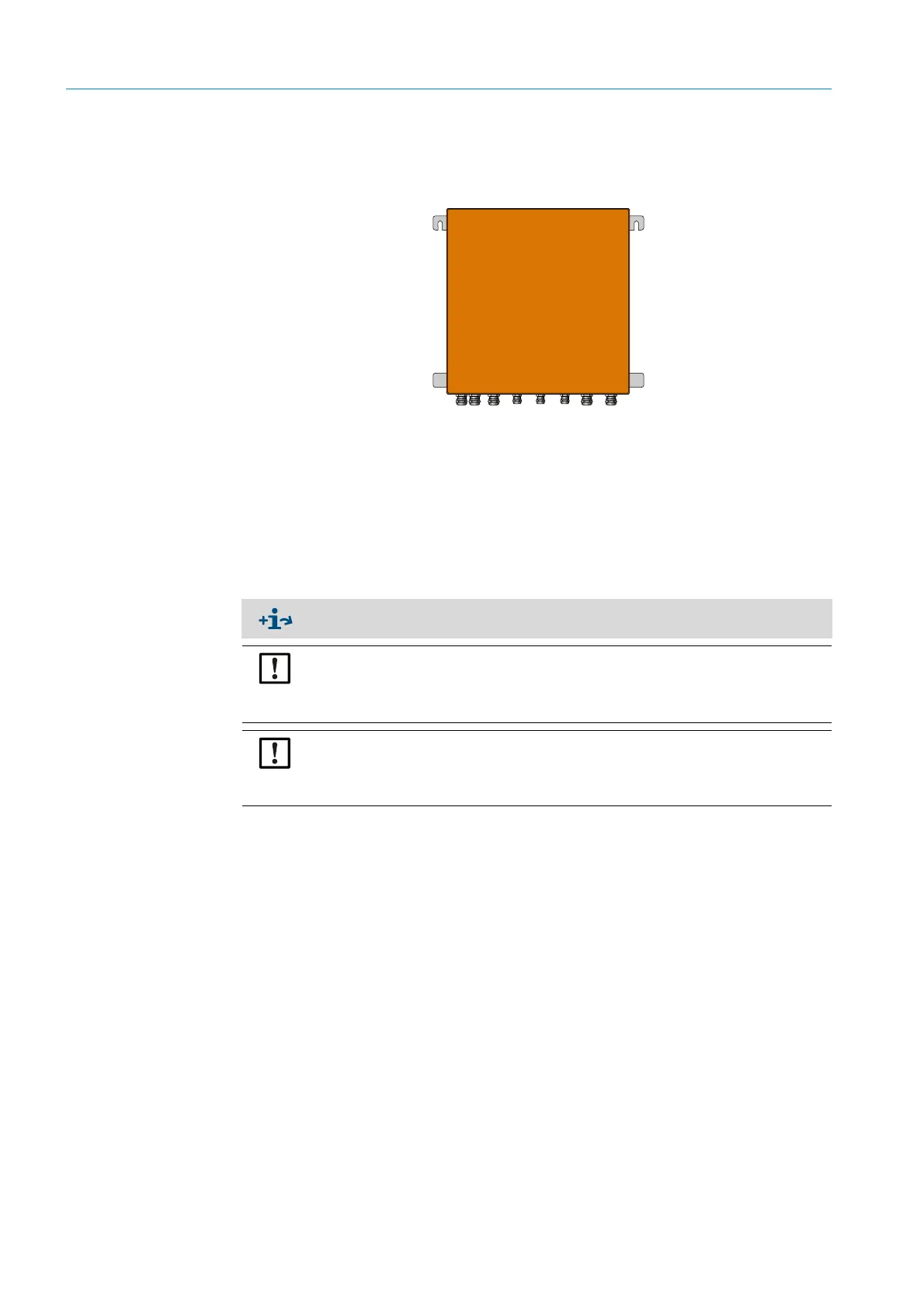
Fig. 8: Connection unit
● Line lengths to the GM32 sender/receiver unit according to project planning.
▸ Provide threaded bolts (4) to screw on the connection unit and screw on the connection
unit, see “Connection unit”, page 76.
!▸
Do not make the electrical connection to the connection unit yet.
3.4 Installing the purge air units
● Length of the purge air hoses to the GM32 according to project planning,
Installing the purge air unit → Operating Instructions of purge air unit.
NOTE: Adequate purge air pressure
▸ Make sure the purge air supply is sufficiently dimensioned to press the purge air into
the gas duct.
If required, please contact SICK Customer Service or your local representative.
NOTE: Observe hose length
Different lengths of the purge air hoses affect the purge air pressure.
If only one purge air unit is used for sender/receiver unit and reflector, the purge air
hoses must have the same length.