17
8012704/YHS4/V2-0/2016-10 | SICK OPERATING INSTRUCTIONS | GM32
Subject to change without notice
PREPARING THE GAS DUCT SIDE 3
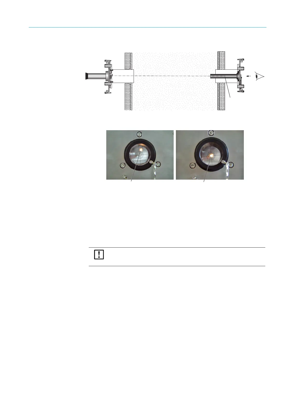
Fig. 6: Alignment of flanges by means of an adjustment device
Fig. 7: Optical alignment display - on the adjustment tube window
– Interchange the adjustment device with light source and the adjustment tube. Align
the flange which contains the adjustment tube again: The light spot must be shown
centrally in the target of the adjustment tube, (see Fig. 7).
5 Perform the final attachment of the “flanges with tube” on the gas duct.
Make sure that the alignment of the flanges does not change.
6 Check the “active measuring path” dimension, the “flange - flange” dimension and the
alignment.
7 Remove the adjustment device again.
8 If necessary, attach duct insulation (protect GM32 from heat).
Light source
Adjustment tube
Align the flange with the
adjustment tube on the
side.
Not aligned correctly Aligned correctly
NOTE: Observe the ambient temperature of the GM32
▸ When the gas duct is hot, insulate the duct and flanges so that the GM32 is pro-
tected from high temperatures, see “System: GM32”, page 65.