16
8012704/YHS4/V2-0/2016-10 | SICKOPERATING INSTRUCTIONS | GM32
Subject to change without notice
3 PREPARING THE GAS DUCT SIDE
3.2.1 Installing the “flanges with tube” on the gas duct
1 Cut openings on the gas duct for the flange with tube.
2 Insert the flange with tube so that the marking (TOP) upwards vertically (irrespective
of the gas duct angle) and attach the flange with tube.
– The tube must project at least 30 mm into the gas duct.
– Make sure other devices or installations do not intersect or interrupt the beam path of
the GM32.
3 Cut the flange opening for the reflector unit accordingly.
Deviation of tube axis between SR-unit and reflector unit: Max. 1°.
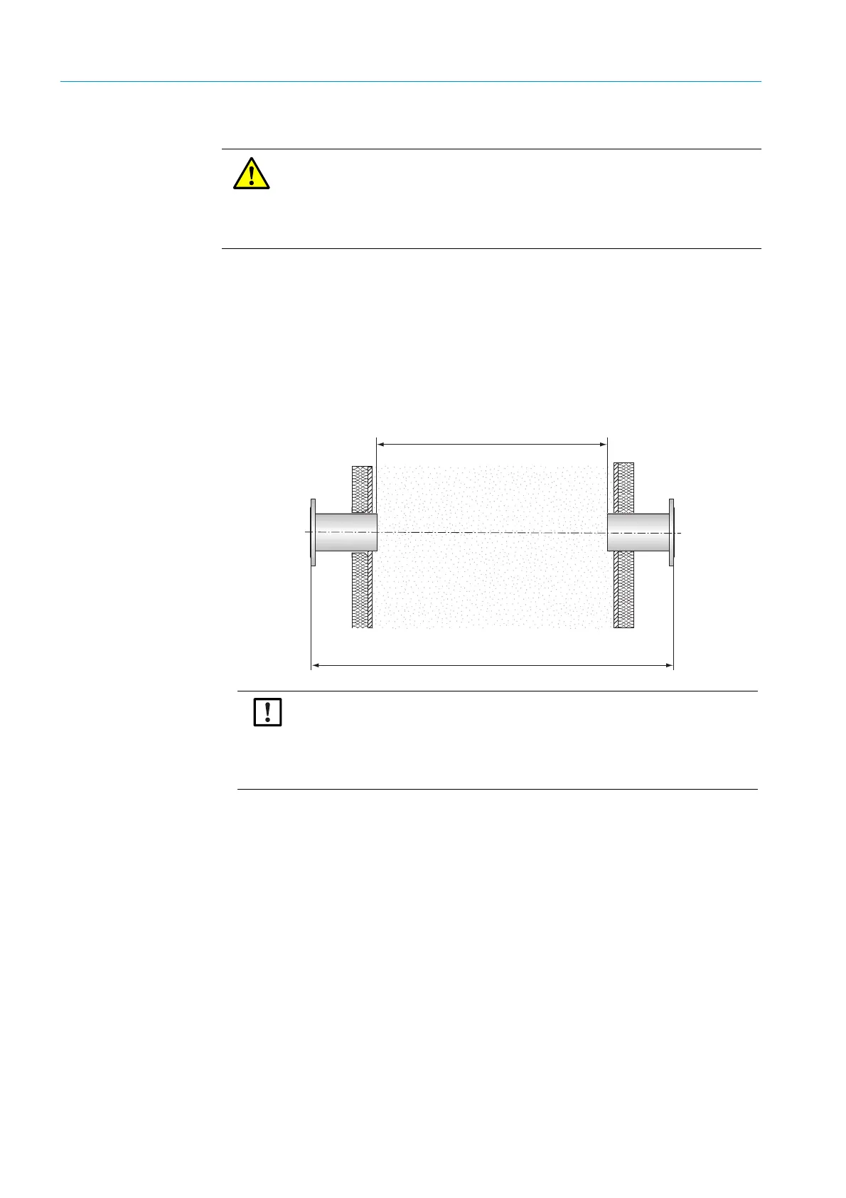
Fig. 5: Flange installation - determination of active measuring path
4 Align the flange visually.
– Remove the protective cap from the adjustment tube.
– Fit the alignment tool (light source on SR-unit side, adjustment tube on reflector side)
onto the flanges, see Fig. 6.
– Look in the window of the adjustment tube and focus the light spot of the light source
by shifting the optical beam tube.
– Align the flange which contains the adjustment tube: The light spot must be shown
centrally in the target of the adjustment tube (see Fig. 7).
WARNING: Hazard through gas escaping out of the gas duct
Hot and/or noxious gases can escape during work on the gas duct, depending on the
plant condition.
▸ Work on the gas duct may only be performed by skilled persons who, based on their
technical training and knowledge as well as knowledge of the relevant regulations,
can assess the tasks given and recognize the hazards involved.
Active measuring path
Active measuring path “flange - flange”
During installation of the “flanges with tube”, the specifications in the test record for
the “flange - flange” and “active measuring path” dimensions must be maintained.
Any deviations up to ±2% can be compensated by the local SICK Customer Service.
Larger deviations of the “flange - flange” dimension require optical readjustment by
the manufacturer, larger deviations of the active measuring path require recalibra-
tion by the manufacturer.