35
8012704/YHS4/V2-0/2016-10 | SICK OPERATING INSTRUCTIONS | GM32
Subject to change without notice
START-UP 4
4.10 Start-up of the purge air supply
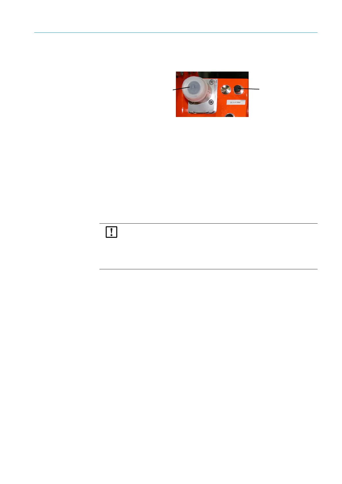
Fig. 22: Connection of the purge air supply
1
Switch on the power supply of the purge air unit on the fuse (fitted by the operator) of the
purge air unit.
– Check the function: A strong air flow must be noticeable.
If it is not noticeable: → Operating Instructions of purge air unit.
– Blow out any dust that may have entered the purge air hose.
2 Check the switch function of the pressure controller in the purge air unit, e.g. by partly
closing off the suction opening of the purge air unit.
The “Purge air signal” warning must be shown.
3 Switch the power supply off again.
4 Connect the purge air hoses with hose clamps to the purge air connection of the SR-unit
and the reflector unit, see Fig. 22, page35. If necessary, remove the protective cap from
the purge air connections.
5 Connect the purge air hoses with hose clamps to the differential pressure sensors.
6 Switch the power supply of the purge air unit on again.
SLV filter monitor terminal
Purge air connection
(shown with protective cap)
The purge air supply protects the measuring system from contamination and overheat-
ing.
▸ Ensure that the purge air pressure is adequate to push the purge air into the gas
duct.
The purge air supply may not be switched off while the gas analyzer is on the gas duct.
▸ Attach clearly visible warnings against accidental switching-off to all switching
devices where the purge air supply can be switched off.