OPERATING INSTRUCTIONS | LFP CUBIC 8019918/ZJA6 / 2017-07-20 | SICK AG
Subject to change without notice
22
6 ELECTRICAL INSTALLATION
6.2 Electrical connection
6.2.1 Overview of the electrical connections
The sensor is connected using a pre-assembled female cable connector with
M12 x 1 plug connector (5/8-pin). With the power switched o, plug the female
cable connector into the sensor and screw it tight.
Connect the cable according to its function. After the supply voltage is set up, the
sensor performs a self-test. Once installed, the sensor is ready for operation upon
completion of the self-test (< 5 s). The display shows the current measured value.
Fig. 5: LFP Cubic
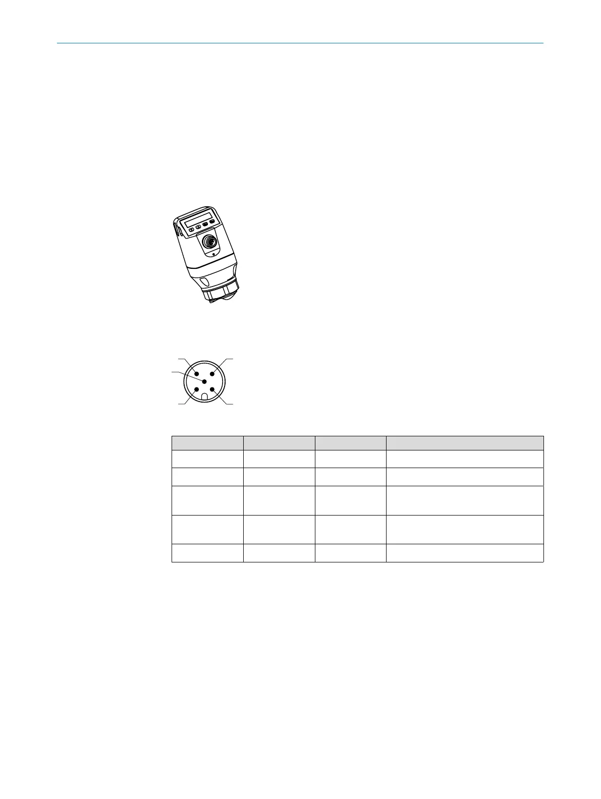
6.2.2 Pin assignment, M12 plug connector, 5-pin
Fig. 6: M12 x 1 plug connector, 5-pin
Contact Marking Wire color Description
1 L+ Brown Supply voltage
2 Q
A
White Analog current/voltage output
3 M Blue Ground, reference potential for
current/voltage output
4 C/Q
1
Black Switching output 1, PNP/ IO-Link
communication
5 Q
2
Gray Switching output 2, PNP/ NPN