OPERATING INSTRUCTIONS | LFP CUBIC 8019918/ZJA6 / 2017-07-20 | SICK AG
Subject to change without notice
12
3 PRODUCT DESCRIPTION
3.2 Product characteristics
3.2.1 Device view
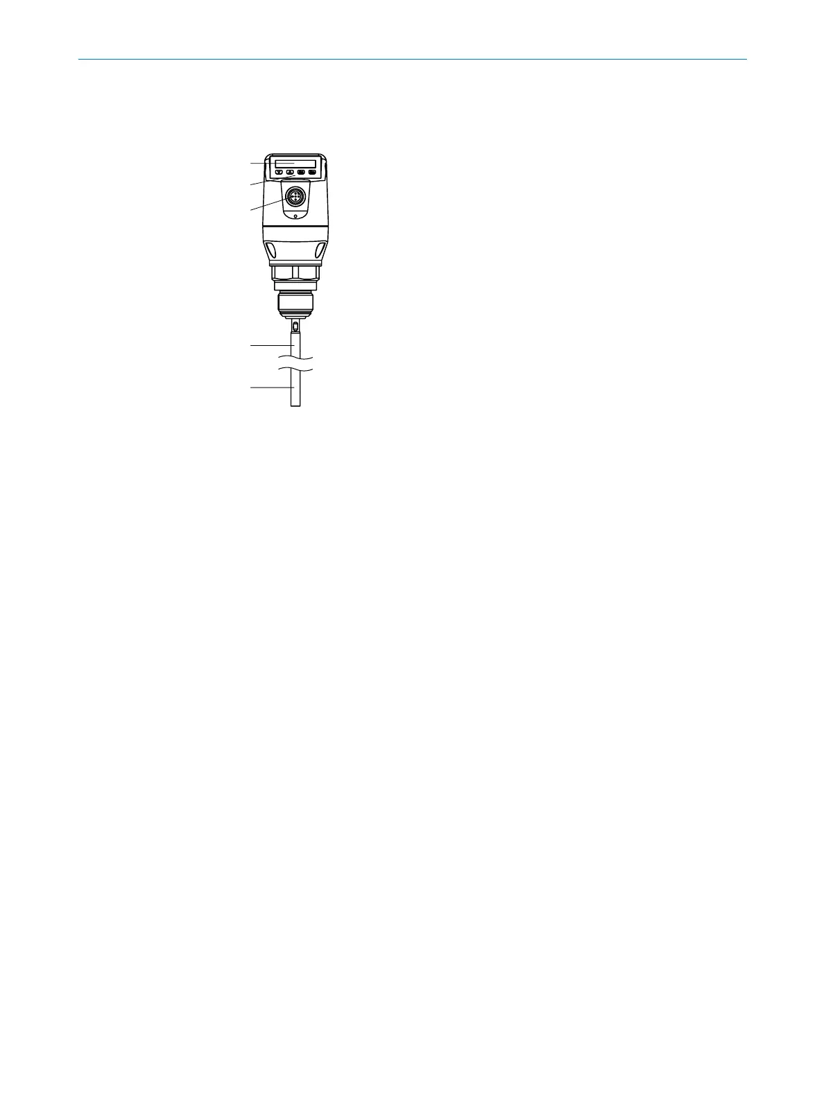
Fig. 1: LFP Cubic (standard version)
1 Sample probe
2 Electrical connection
3 Operating buttons
4 Display
3.2.2 Operating buttons
The sensor is operated using the display and operating buttons.
For a detailed description of the pushbuttons and their functions, see “8.1 Display and
pushbuttons”.
3.3 Product features and functions
3.3.1 Principle of operation
The LFP uses TDR (Time Domain Reectometry) technology.
This is a process to determine transit times of electromagnetic waves. The sensor
electronics generate a low-energy electromagnetic pulse, which is linked to and runs
along the probe.
If this pulse strikes the surface of the liquid to be measured, a portion of the pulse
is reected there and is conducted back up along the probe path to the electronics,
which then calculate the level based on the time dierence between the sent and the
received pulse.
The sensor can output this level as a continuous measured value (analog output) and
can also derive two and/or four freely positionable switching points from it (switching
outputs).
IO-Link communication is also available for the switching output (Q1),
see “8.1.3 IO-Link”.