OPERATING INSTRUCTIONS | LFP CUBIC 8019918 /ZJA6/ 2017-07-20 | SICK AG
Subject to change without notice
23
6ELECTRICAL INSTALLATION
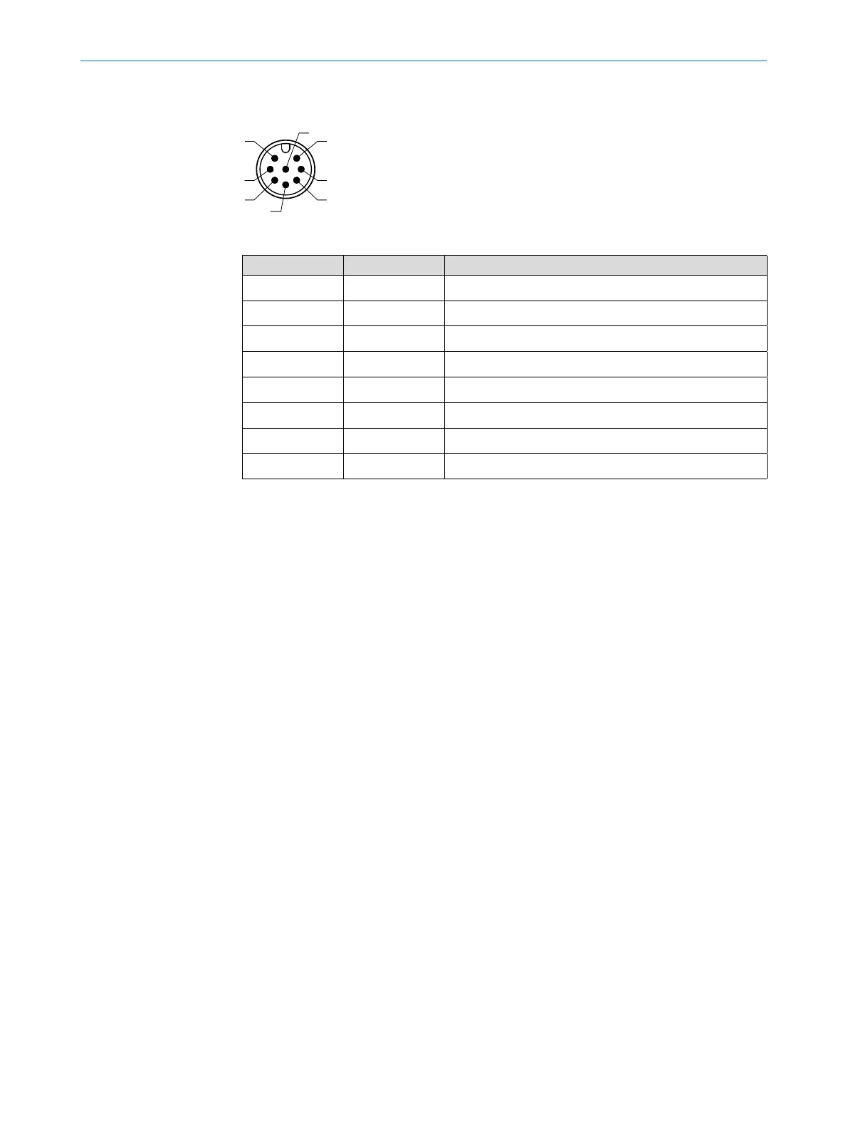
6.2.3 Pin assignment, M12 plug connector, 8-pin
2
3
4
1
7
6
Fig. 7: M12 x 1 plug connector, 8-pin
Contact Marking Description
1 L+ Supply voltage
2 Q
2
Switching output 2, PNP/ NPN
3 M Ground, reference potential for current/voltage output
4 C/Q
1
Switching output 1, PNP/IO-Link communication
5 Q
3
Switching output 3, PNP/NPN
6 Q
4
Switching output 4, PNP/NPN
7 Q
A
Analog current/voltage output
8 No function
The wire colors for 8-pin cables are not standardized. Always note the pin assignment
of the sensor.