7SR210 & 7SR220 Configuration Guide
Unrestricted Page 12 of 14 © 2018 Siemens Protection Devices Limited
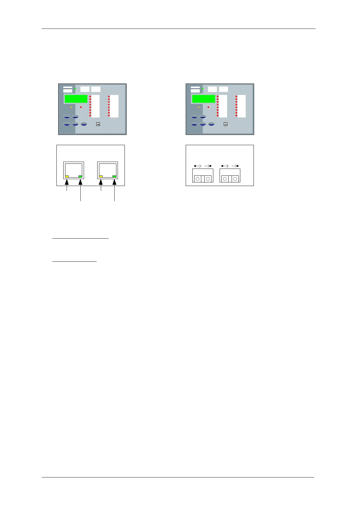
2.1.6 OPTIONAL REAR EN100 ETHERNET MODULE
Connections are made on the rear underside of the relay either RJ45 sockets (electrical) or Duplex LC
(fibre optic) connectors depending on the option ordered.
LED yellow
LED green
LED yellow
LED green
Ch 1 Ch 2
Ethernet – EN100-E
EN100 Module – RJ45 Interface
Ethernet – EN100-O
Ch 1 Ch 2
EN100 Module – Duplex-LC Interface
Green LED (Physical Link)
Off – No link
On – Link present
Yellow LED (Activity)
Off – No traffic
On/flashing - Traffic
Figure 2.1.6-1 EN100 Ethernet Module
2.1.7 CONFIGURING RELAY DATA COMMUNICATION
Using the keys on the relay fascia scroll down the settings menu’s into the ‘communications’ menu and change
the settings for the communication port used on the relay. All of the below settings may not be available in all
relay types. Reydisp Evolution software uses IEC60870-5-103 protocol to communicate.
COM1 – Standard RS485 Rear Port
COM2 - USB Port
COM3 – Optional Fibre Optic, RS485, RS232 or Ethernet Port
COM4 – Additional (Optional) Rear Connection**
LAN – Optional Ethernet Ports