Chapter 4 - Data Communications Definitions
© 2017 Siemens Protection Devices Limited Chapter 4 - Page 79 of 96
Deadband
Counters
Static (Steady-State) Object Number: 20
Change Event Object Number: 22
Static Variation reported when variation 0 requested: 1 (32-Bit Counter with Flag)
or 2 (16-Bit Counter with Flag)
or 5 (32-Bit Counter w/o Flag)
or 6 (16-Bit Counter w/o Flag)
Change Event Variation reported when variation 0 requested: 1 (32-Bit Counter Event with Flag)
or 2 (16-Bit Counter Event with Flag)
or 5 (32-Bit Counter Event with Flag and Time)
or 6 (16-Bit Counter Event with Flag and Time)
Frozen Counters
Static (Steady-State) Object Number: 21
Change Event Object Number: 23
Static Variation reported when variation 0 requested: 1 (32-Bit Frozen Counter with Flag)
or 2 (16-Bit Frozen Counter with Flag)
or 5 (32-Bit Frozen Counter with Flag and Time)
or 6 (16-Bit Frozen Counter with Flag and Time)
or 9 (32-Bit Frozen Counter w/o Flag)
or 10 (16-Bit Frozen Counter w/o Flag)
Change Event Variation reported when variation 0 requested: 1 (32-Bit Frozen Counter Event with Flag)
or 2 (16-Bit Frozen Counter Event with Flag)
or 5 (32-Bit Frozen Counter Event with Flag and Time)
or 6 (16-Bit Frozen Counter Event with Flag and Time)
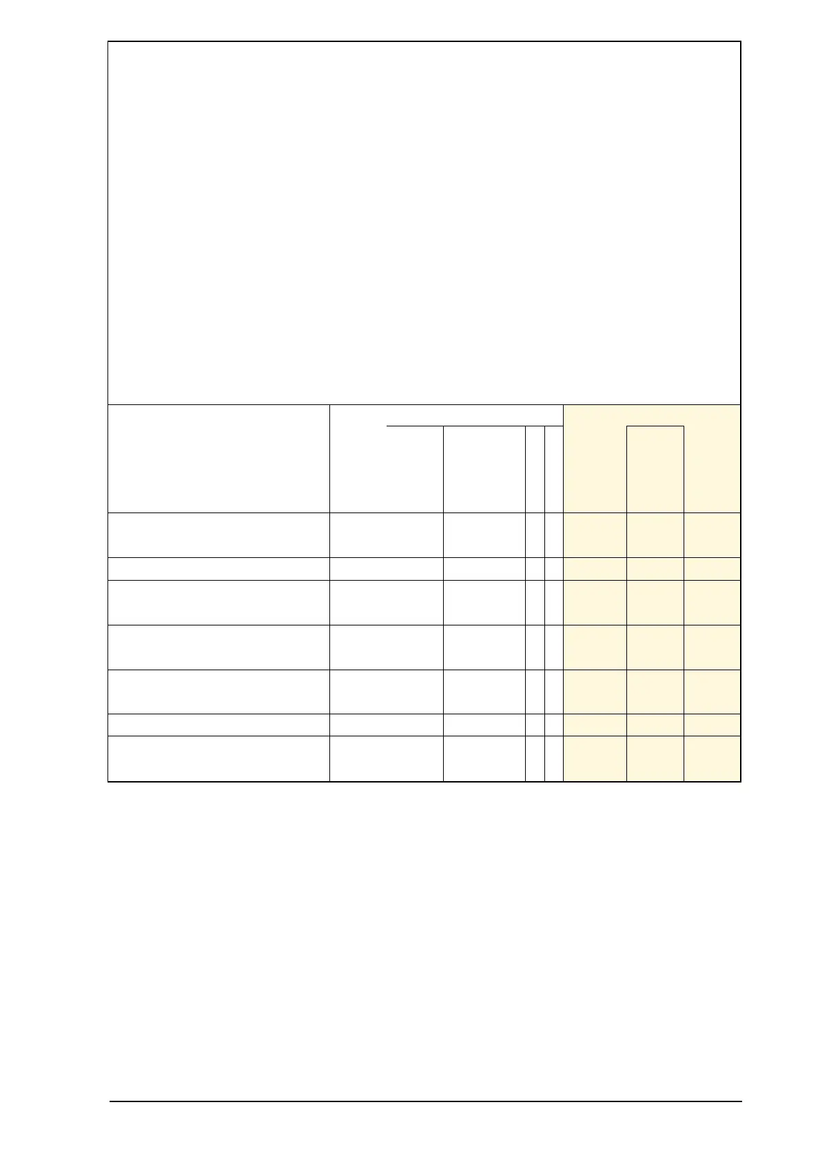
Point
Description
Index
Default
Change
Event
Assigned
Class
(1, 2, 3
or none)
Counter
Frozen Counter
Default
Variation
Static
Object 20
Default
Variation
Event
Object 22
Is Resettable
IsFreezable
Default
Change
Event
Assigned
Class
(1, 2, 3
or none)
Default
Variation
Static
Object 21
Default
Variation
Event
Object 23
25 E5 Counter 0,3 5 1 1
✔
0,2 9 1
26 E6 Counter 0,3 5 1 1
✔
0,2 9 1
27 E7 Counter 0,3 5 1 1
✔
0,2 9 1
28 E8 Counter 0,3 5 1 1
✔
0,2 9 1
29 E9 Counter 0,3 5 1 1
✔
0,2 9 1
30 E10 Counter 0,3 5 1 1
✔
0,2 9 1
31 E11 Counter 0,3 5 1 1
✔
0,2 9 1
32 E12 Counter 0,3 5 1 1
✔
0,2 9 1
33 E13 Counter 0,3 5 1 1
✔
0,2 9 1
34 E14 Counter 0,3 5 1 1
✔
0,2 9 1
35 E15 Counter 0,3 5 1 1
✔
0,2 9 1
36 E16 Counter 0,3 5 1 1
✔
0,2 9 1
5.3.5 Analog Inputs
The following table lists Analog Inputs (Object 30). It is important to note that 16-bit and 32-bit variations of Analog
Inputs, Analog Output Control Blocks, and Analog Output Statuses are transmitted through DNP as signed numbers.
The “Default Deadband,” and the “Default Change Event Assigned Class” columns are used to represent the absolute
amount by which the point must change before an Analog change event will be generated, and once generated in
which class poll (1, 2, 3, or none) will the change event be reported.
The default analog input event buffer size is set 30. The analog input event mode is set to Most Recent, only most
recent event for each point is stored.
Analog inputs are by default returned in a class zero interrogation.
Note, not all points listed here apply to all builds of devices.