7SR210 & 7SR220 Applications Guide
© 2013 Siemens Protection Devices Limited Page 39 of 48
5.3 Voltage Transformer Supervision (60VTS)
Although VTs rarely fail themselves, VT Supervision presents a common application because of the failure of
protective Fuses connected in series with the VTs.
When a VT failure occurs on one or two phases, the voltage levels seen by the protection become unbalanced. A
large level of NPS voltage is therefore detected - around 0.3 x Vn for one or two VT failures. However this
condition would also occur for a system fault. To differentiate between the two conditions, the element uses NPS
current to restrain the VTS algorithm as show in the accompanying table.
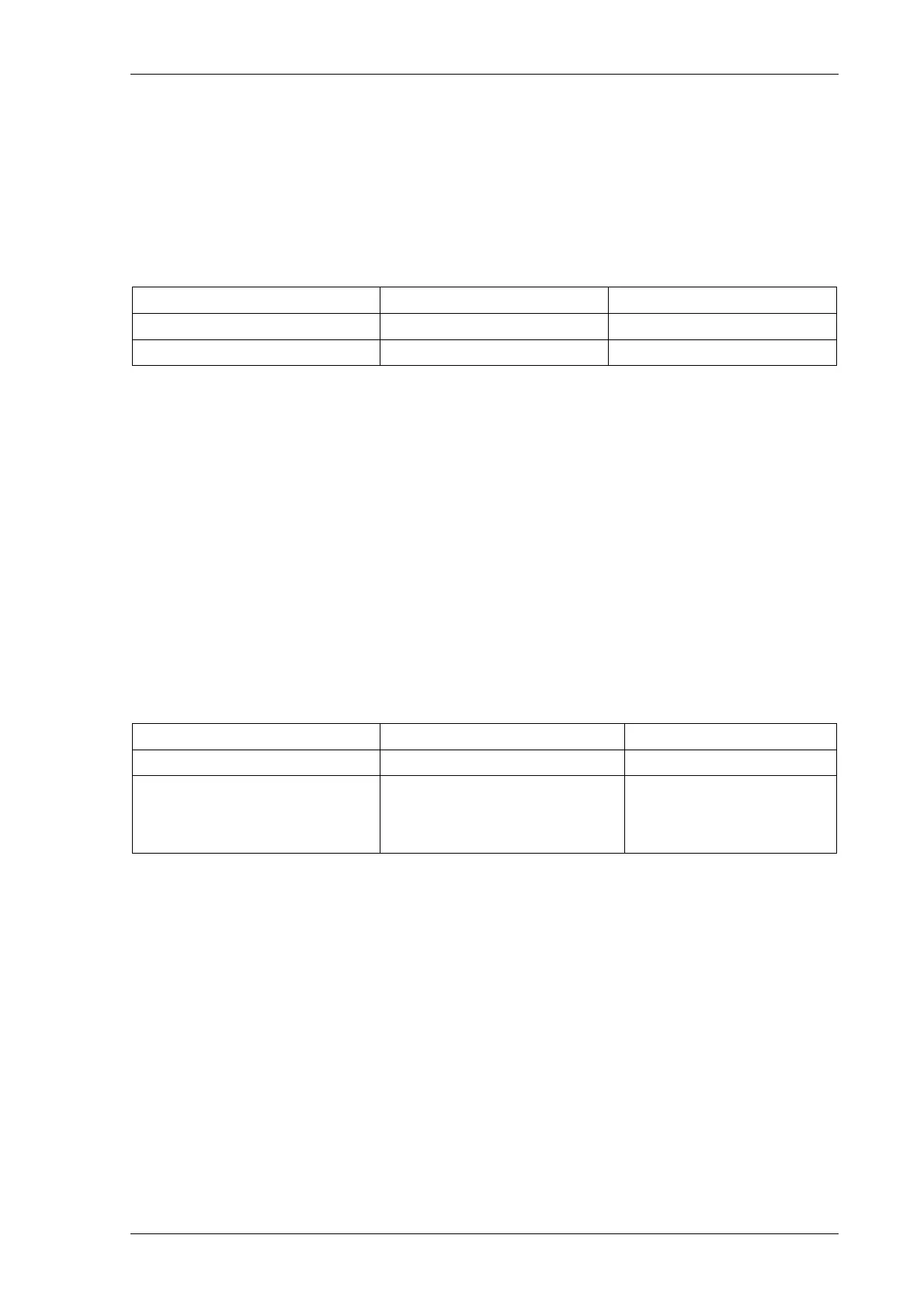
NPS Voltage NPS Current Decision
> Setting > Setting System Fault
> Setting < Setting VT Failure
Table 5-3 Determination of VT Failure (1 or 2 Phases)
Following a VT Failure, the level of NPS current would be dependent solely upon load imbalance - perhaps 0.1 x
In as a maximum.
Operation is subject to a time delay to prevent operation for transitory effects.
NPS voltage and current quantities are used rather than ZPS since the latter makes it difficult to differentiate
between a VT failure and a Phase-Phase fault. Both conditions would generate little or no ZPS current. However
the element provides an option to use ZPS quantities to meet some older specifications.
There are possible problems with using NPS quantities due to load imbalances. These would also generate
significant levels of NPS current and so possibly cause a VT failure to be missed. This problem can be overcome
by careful selection of settings, however, setting the NPS current threshold above the level expected for
imbalance conditions.
If a failure occurs in all 3 Phases of a Voltage Transformer, then there will be no NPS or ZPS voltage to work with.
However the PPS Voltage will fall below expected minimum measurement levels.
This could also be due to a ‘close in’ fault and so PPS Current must remain above minimum load level BUT below
minimum fault level.
PPS Voltage PPS Current Decision
< Setting > Minimum Fault Level System Fault
< Setting Minimum Load Level <
AND
< Minimum Fault Level
VT Failure
Table 5-4 Determination of VT Failure (3 Phases)
Operation is again subject to a time delay to prevent operation for transitory effects.
Alternatively a 3 Phase VT failure can be signalled to the relay via a Binary Input taken from the Trip output of an
external MCB. This can also be reset by a Binary Input signal.
VTS would not normally be used for tripping - it is an alarm rather than fault condition. However the loss of a VT
would cause problems for protection elements that have voltage dependant functionality. For this reason, the
relay allows these protection elements - under-voltage, directional over-current, etc. - to be inhibited if a VT failure
occurs.