7SR210 & 7SR220 Commissioning & Maintenance Guide
© 2013 Siemens Protection Devices Limited Page 27 of 82
2.3 Derived Earth Fault (67/50N, 67/51N)
7SR22
46
BC
46
NPS
(x2)
37
(x2)
49
50
BF
V
L1
(V
A
)
V
L2
(V
B
)
V
L3
(V
C
)
V
4
(V
X
)
I
L1
(I
A
)
81
HBL
2
37
(x2)
49
50
BF
I
L2
(I
B
)
81
HBL
2
37
(x2)
49
50
BF
I
L3
(I
C
)
81
HBL
2
60
CTS
I
4
(I
G
)
I
5
(I
SEF
)
74
TCS
NOTE: The use of some
functions are mutually exclusive
67/
50
(x4)
67/
51
(x4)
67/
50N
(x4)
67/
50
(x4)
67/
50
(x4)
67/
51
(x4)
67/
51
(x4)
67/
51N
(x4)
67/
50G
(x4)
67/
51G
(x4)
67/
50S
(x4)
67/
51S
(x4)
64
H
27
59
27
59
(x4)
27
59
(x4)
27
59
(x4)
47
(x2)
81
(x6)
79
Optional
59N
(x2)
81
HBL
2N
60
VTS
51V
51V
51V
37G
(x2)
37S
(x2)
51c
60
CTS-
I
60
CTS-
I
60
CTS-
I
37
50
BF
37
50
BF
25
50
AFD
50
AFD
50
AFD
51c
51c
51c
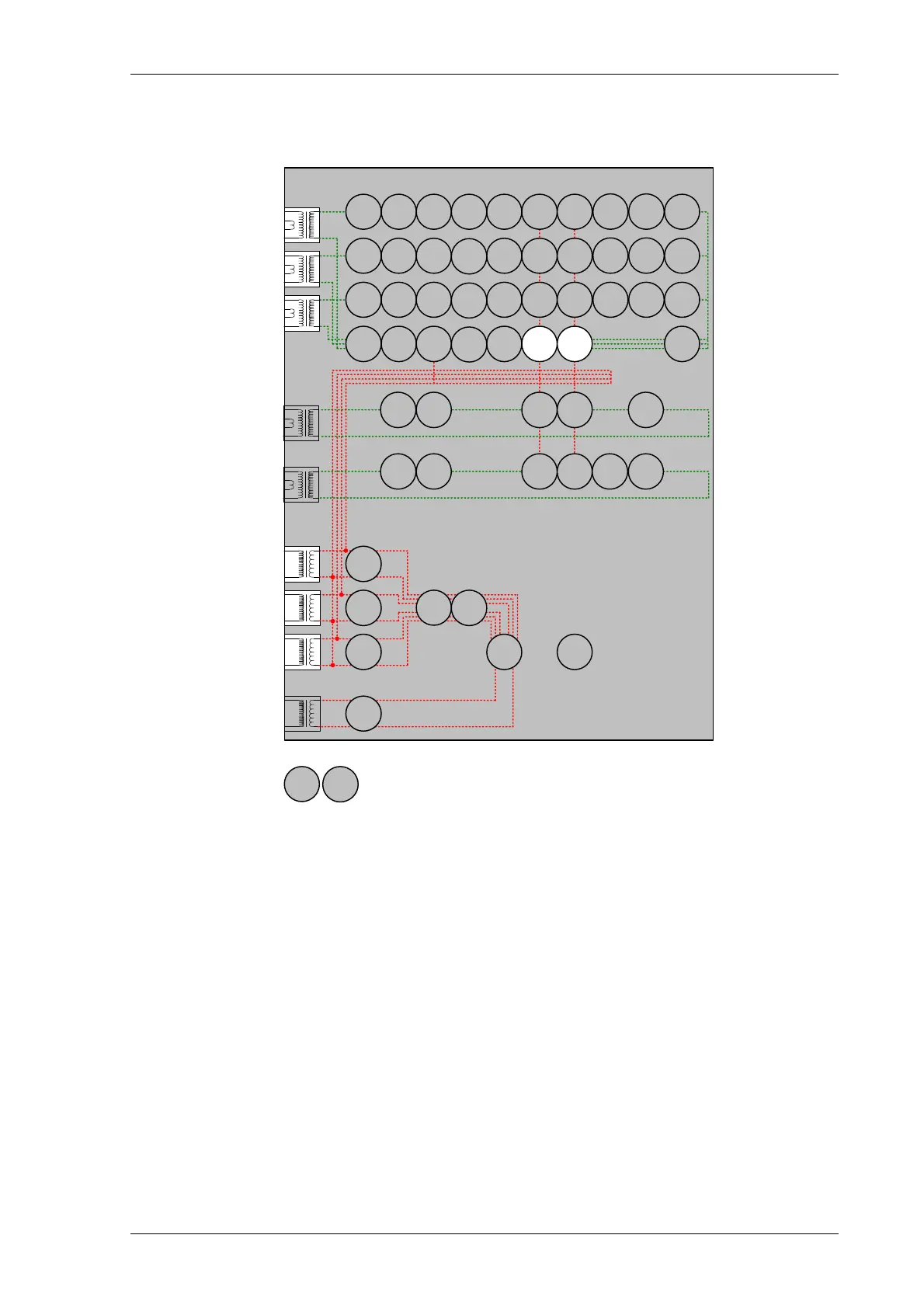
Figure 2.3-1 Derived Earth Fault
Voltage Inputs: V
L1
(V
A
), V
L2
(V
B
), V
L3
(V
C
)
Current Inputs: I
L1
(I
A
), I
L2
(I
B
), I
L3
(I
C
),
Disable: 37, 46, 49, 60CTS, 50BF, 60CTS, 46BC, 79
Map Pickup LED: 51N-n/50N-n - Self Reset
Other protection functions may overlap with these functions during testing; it may be useful to disable some
functions to avoid ambiguity. Derived EF, Measured EF Sensitive EF & Restricted EF protections can be
Enabled/Disabled individually or as groups in the ‘Function Config’ menu.
Derived EF elements can be separated from Measured EF and sensitive EF by arrangement of the secondary
injection circuit by shorting/disconnecting I
4
and I
5
inputs.
If any of these elements are defined as directional the correct voltage phase direction will be required to produce
an operation of those elements.