7SR210 & 7SR220 Description of Operation
Unrestricted ©2018 Siemens Protection Devices Limited Page 15 of 94
Section 2: Hardware Description
2.1 General
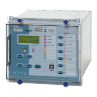
The structure of the relay is based upon the Multi-function hardware platform. The relays are supplied in either
size E6 or size E8 cases (where 1 x E = width of 26 mm). The hardware design provides commonality between
products and components across the Multi-function range of relays.
Table 2.1-1 Summary of Overcurrent Relay Configurations
Relay Current
Inputs
Voltage
Inputs
Binary
Inputs
Output
Relays
LEDs Function
Keys
Case
7SR2102 4 9 8 8 E6
7SR2103 4 19 16 16 E8
7SR2104 4 19 16 8 6 E8
7SR2105 4 39 16 32 E12
7SR2106 4 39 16 16 12 E12
7SR2202 5 4 3 6 8 E6
7SR2203 5 4 13 14 16 E8
7SR2204 5 4 13 14 8 6 E8
7SR2205 5 4 33 14 32 E12
7SR2206 5 4 33 14 16 12 E12
Relays are assembled from the following modules: -
1. Front Fascia with three fixed function LEDs and ordering options of configurable LEDs/Function Keys.
2. Processor module
3. Analogue Input module, either
· 4 x Current + 6 x Binary Inputs + 2 x Binary Outputs (7SR21), or
· 5 x Current + 4 x Voltage (7SR22).
4. Power Supply and 3 x Binary Inputs (BI) and 6 x Binary Outputs (BO).
5. Optional Binary Input/Output Module
· 10 x Binary Inputs + 8 x Binary Outputs
· 20 x Binary Inputs
6. Optional Communications Module (2x rear fibre optic + 1x IRIG-B ports), (1x rear RS485 + 1x IRIG-B
port), (1x rear RS232 + 1x IRIG-B port), (2x Electrical Ethernet for IEC 61850), (2x Optical Ethernet for
IEC 61850).

 Loading...


