7SR210 & 7SR220 Commissioning & Maintenance Guide
© 2013 Siemens Protection Devices Limited Page 51 of 82
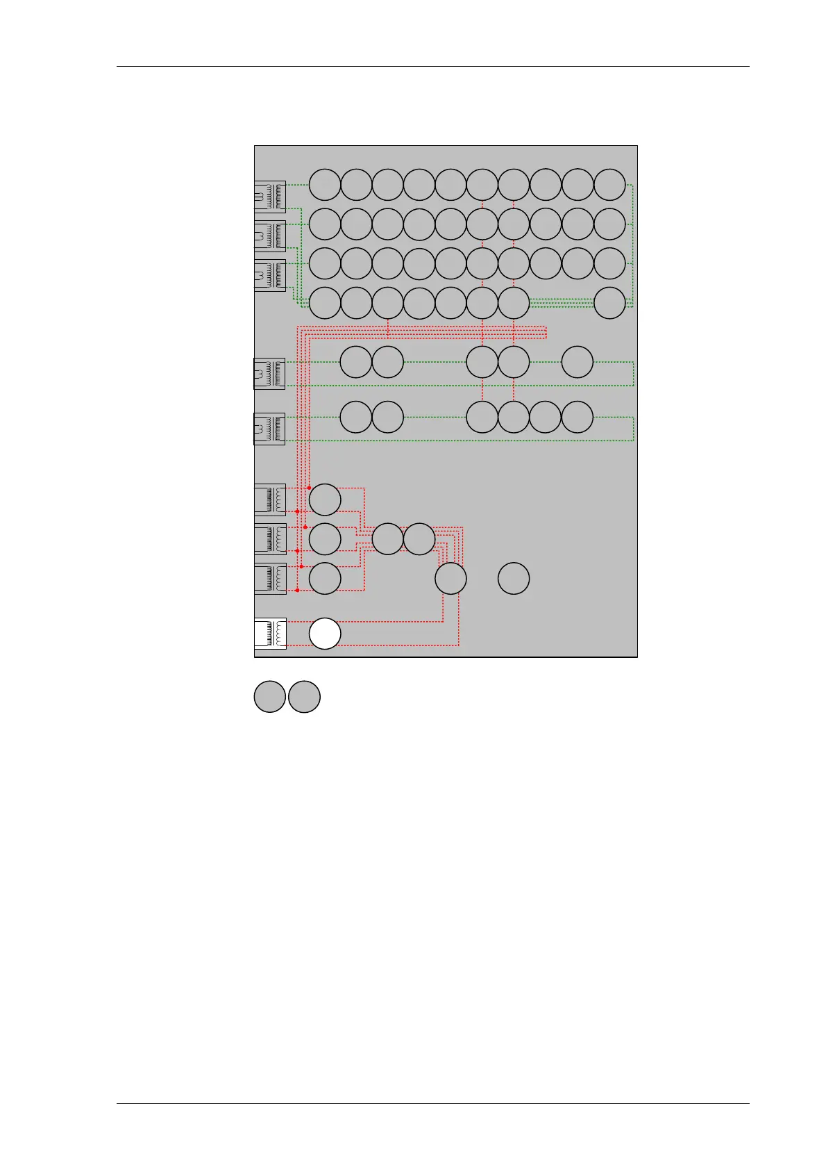
2.10.3 VX Under/Over Voltage. (Vx 27/59)
7SR22
46
BC
46
NPS
(x2)
37
(x2)
49
50
BF
V
L1
(V
A
)
V
L2
(V
B
)
V
L3
(V
C
)
V
4
(V
X
)
I
L1
(I
A
)
81
HBL
2
37
(x2)
49
50
BF
I
L2
(I
B
)
81
HBL
2
37
(x2)
49
50
BF
I
L3
(I
C
)
81
HBL
2
60
CTS
I
4
(I
G
)
I
5
(I
SEF
)
74
TCS
NOTE: The use of some
functions are mutually exclusive
67/
50
(x4)
67/
51
(x4)
67/
50N
(x4)
67/
50
(x4)
67/
50
(x4)
67/
51
(x4)
67/
51
(x4)
67/
51N
(x4)
67/
50G
(x4)
67/
51G
(x4)
67/
50S
(x4)
67/
51S
(x4)
64
H
27
59
27
59
(x4)
27
59
(x4)
27
59
(x4)
47
(x2)
81
(x6)
79
Optional
59N
(x2)
81
HBL
2N
60
VTS
51V
51V
51V
37G
(x2)
37S
(x2)
51c
60
CTS-
I
60
CTS-
I
60
CTS-
I
37
50
BF
37
50
BF
25
50
AFD
50
AFD
50
AFD
51c
51c
51c
Figure 2.10-2 Vx Under/Over Voltage
Voltage Inputs: V
4
(V
X
)
Current Inputs: n/a apply zero current to stabilize other functions
Disable:
Map Pickup LED:. Vx 27/59 - Self Reset
If DTL setting is small, gradually increase single phase voltage applied to Vx input until element operates if the
element is Overvoltage. Alternatively, if the element is Undervoltage, increase single phase voltage applied to Vx
input until element operates.
If DTL is large, for Overvoltage elements, apply 0.9x setting, check for no operation, apply 1.1x setting, check
operation. For Undervoltage elements, apply 1.1x setting, check for no operation, apply 0.9x setting, check
operation.
Apply 2x setting voltage if possible and record operating time.
Starting with the element in the operated condition, gradually increase or decrease the applied voltage until the
element resets. Measure the reset voltage level to check the 27/59 Hysteresis setting.