The fire control panel is approved with the batteries listed above, use only
Siemens provided batteries.
6.5 Connection overview
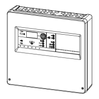
The picture below shows the overview of the panel connection.
Fig. 7: Connection overview of FC360 fire control panel
Panel type specific. Only FC362-xx supports two loops.
Connection of sounder lines
Aux. power supply DC 24 V/0.2 A
Configurable IO, default setting as 'Input'
Configurable IO, default setting as 'Unmonitored output'
Output relay, default setting as 'RT fire'
Output relay, default setting as 'RT fault'
Output relay, default setting as 'Fire alarm'
Connection of ↑ detector lines (FC361-xx: 1 loop/2 stubs;
FC362-xx: 2 loops/4 stubs)
 Loading...