The current configurations have been backed up to a PC. See Backing up
configurations to the PC [➙ 117].
The power supplies (mains and battery) are disconnected.
All connectors are disconnected (label cables before disconnecting them).
RS232/RS485 module is removed if installed.
The mainboard is removed. Refer to document A6V10450593, see chapter
'Applicable documents [➙ 9]'.
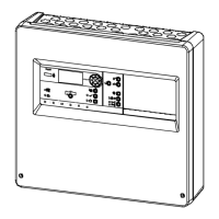
1. Mount the mainboard (3) with the 6 screws (2) to the threaded bolts (1) that are
embedded in the rear panel.
2. Re-install RS232/RS485 module that may have been removed.
3. Connect all connectors according to the label.
4. Switch on power supply.
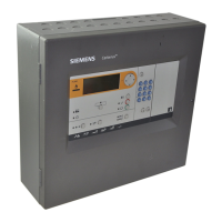
The panel starts up.
5. Set country and language, and then press when an auto configuration
message pops up on the screen.
6. Check firmware version and ensure the latest version is installed. It is an
integral part of ‘FC360 Desktop Editor 2.0’ which can be downloaded from
www.siemens.com/cerberus-fit.
7. Apply configuration to the panel if you have it on PC. See 'Applying
configurations to the panel [➙ 117]'.
8. Perform function test. See 'Function test [➙ 113]'.
9. Execute completing work. See 'Completing work [➙ 113]'.
 Loading...