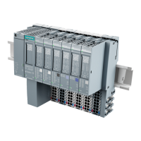
Terminal modules
1.2 Terminal modules TM-P15S23-A0, TM-P15C23-A0 and TM-P15N23-A0 (6ES7193-4CDx0-0AA0)
ET 200S
Manual, Edition 10/2005, A5E00514527-01
1-3
1.2 1.2 Terminal modules TM-P15S23-A0, TM-P15C23-A0 and
TM-P15N23-A0 (6ES7193-4CDx0-0AA0)
Properties
• Terminal module for power modules
• Infeed for a new potential group up to the next TM-P terminal module
• Available in two variants: screw terminal, spring terminal, "fast connect" quick connection
method without stripping
• The signal assignment of the AUX1 bus is specified by the feed to the power module of
this potential group.
• Interrupted AUX1 bus without electrical connection to the next potential group to the left
• Access to the AUX1 potential through terminals A4 and A8
Block diagram
Block diagram for the TM-P15S23-A0, TM-P15C23-A0, and TM-P15N23-A0 terminal
modules
1
2
3
4
5
37
48
26
PM-E
AA
(1) Backplane bus
(2) Infeed of the power buses to the electronic modules
(3) Terminals with connection to the power module
(4) Use of terminals A4 and A8 as protective conductor terminals or potential terminals of any
kind
(5) Infeed of the AUX1 bus by means of terminals A4 and A8

 Loading...


