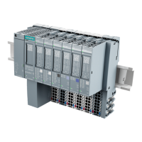
Terminal modules
1.13 TM-C120S and TM-C120C terminal modules (6ES7193-4DLx0-0AA0)
ET 200S
1-18 Manual, Edition 10/2005, A5E00514527-01
1.13 1.13 TM-C120S and TM-C120C terminal modules (6ES7193-4DLx0-0AA0)
Properties
• Terminal module for the COMPACT modules
• available in two variants: screw terminal, spring terminal
• The COMPACT module determines the assignment to terminals 1 to 80.
• Infeed of the power buses to the electronic modules from the last potential group of the
COMPACT module
• uninterrupted AUX1 bus
• No access to the AUX1 potential through terminals
• with 40-pin supplementary terminal; any additional required potentials can be applied
there
Block diagram
Block diagram of the TM-C120S and TM-C120C terminal modules
/
0
/
0
&203$&7PRGXOH
1
2
3
(1) Backplane bus
(2) Infeed of the power buses to the electronic modules
(from the last potential group of the COMPACT module)
(3) Terminals with connection to the COMPACT module
TM-C120x Technical Specifications (6ES7193-4DLx0-0AA0)
Dimensions and Weight
Dimensions W × H × D (mm)
• Screw-type/spring terminals
120 × 132 × 43
Weight Approx. 335 g

 Loading...


