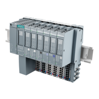
Digital electronic modules
3.9 4DI NAMUR digital electronic module (6ES7131-4RD01-0AB0)
ET 200S
Manual, Edition 10/2005, A5E00514527-01
3-39
Permissible potential difference
• Between different circuits
75 VDC, 60 VAC
Insulation test voltage:
• Channels against the backplane bus and
load voltage
500 VDC
• Load voltage against the backplane bus
500 VDC
Current consumption
• From load voltage L+
Dependent on the sensor
Power dissipation of the module Typically 1.6 W
Parameter length 12 bytes
Status, interrupts, diagnostics
Status display Green LED per channel
Interrupts
• Hardware interrupt
• Diagnostic interrupt
no
Yes, can be set
Diagnostics function
• Group error display
• Diagnostic information can be displayed
Red "SF" LED
supported
Monitoring for
• Short circuit
• Wire break
I > 7 mA
1
I > 0.35 mA
1
Data for selecting a sensor
Input current for NAMUR sensors to NAMUR or EN 50227
• At signal "1"
• At signal "0"
2.1 mA to 7 mA
0.35 mA to 1.2 mA
Input current for a closed contact
• At signal "1"
2.1 mA to 7 mA
• For signal "0"
0.35 mA to 1.2 mA
Input current for an open contact
• At signal "1"
Typ. 8 mA
• Permitted bias current
0.5 mA
Input delay
• At "0" to "1"
max. 4.6 ms
• At "1" to "0"
max. 4.6 ms
Tolerated switchover time with changeover
contacts
300 ms
Parallel connection of inputs no
Sensor power supply outputs
Number of outputs 1
Output voltage
• With load
min. 8.2 V
Output current
• Rated value
45 mA
Additional (redundant) supply Not permitted
Short-circuit protection Yes, electronic
1
Only for NAMUR sensors and closed contacts.

 Loading...


