Digital electronic modules
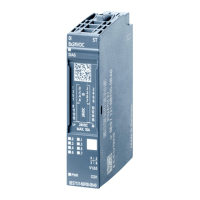
3.12 2DO 24 VDC/0.5 A Standard digital electronic module (6ES7132-4BB01-0AA0)
ET 200S
Manual, Edition 10/2005, A5E00514527-01
3-51
Galvanic isolation
• Between the channels
no
• Between the channels and backplane bus
Yes
Permissible potential difference
• Between the different circuits
75 VDC / 60 VAC
Insulation tested 500 VDC
Current consumption
• From the load voltage L+ (no load)
max. 5 mA per channel
Power dissipation of the module Typically 0.4 W
Status, interrupts, diagnostics
Status display Green LED per channel
Diagnostics function no
Data for selecting an actuator
Output voltage
• At signal "1"
min. L+ (-1 V)
Output current
• At signal "1"
– Rated value
– Permitted range
0.5 A
7 mA to 0.6 A
• With signal "0" (leakage current)
max. 0.3 mA
Output delay (for resistive load)
• at "0" to "1"
max. 200 µs
• At "1" to "0"
max. 1.3 ms
Load resistor range 48 Ω to 3.4 kΩ
Lamp load max. 5 W
Connecting two outputs in parallel
• For redundant triggering of a load
Yes (per module)
• To increase performance
no
Control of a digital input Yes
Switch rate
• For resistive load
100 Hz
• On inductive load
2 Hz
• For lamp load
10 Hz
Limitation (internal) of the voltage induced on
circuit interruption
Typically L+ (-55 to -60 V)
Reverse-voltage proof Yes, if using the same load voltage as at the
power module
Short-circuit protection of the output Yes
2
• Threshold on
Typ. 0.7 A to 1.8 A
1
Polarity reversal can lead to the digital outputs being connected through.
2
Per channel



 To Next Page