Process interfacing via an automation system (PLC, PC)
9.4 Control with FB 79
SIMATIC MV500
180 Operating Instructions, 03/2021, C79000-G8976-C494-05
Note
Reaction when an error occurs
After an error has occurred, you will need to set the "SEL0" to "SEL3" signals and the "TRN"
signal to "0"
and then reset the error with the "RES" signal. The "DISA" signal must have the
value "1" (no edge change).
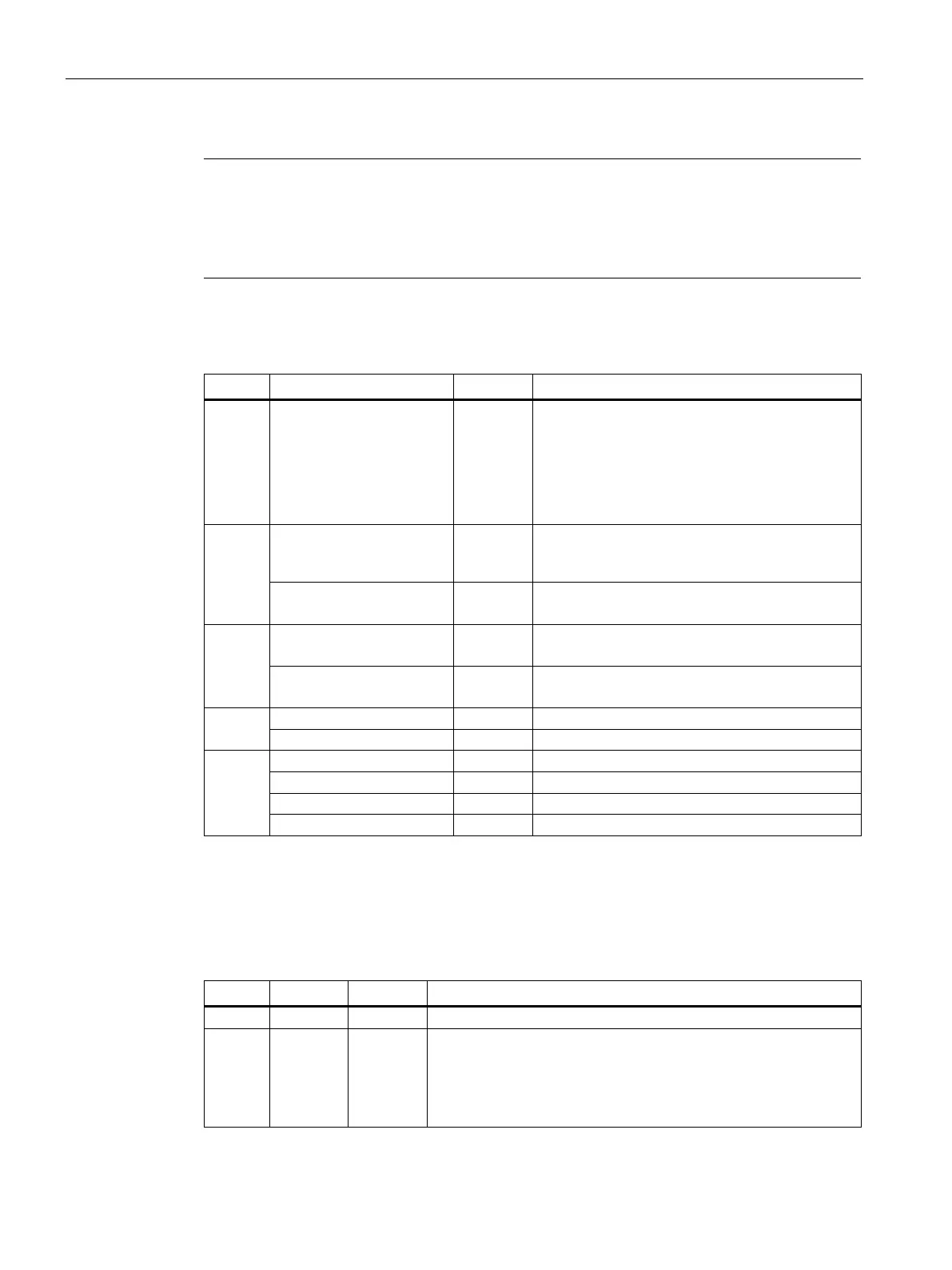
Table 9- 40 Sequence when saving the program
Apply for at least 100 ms:
SEL0 = 1
SEL1 = 1
SEL2 = 0
Disable keyboard control. DISA must have the
value 1. No edge change is necessary.
Select program to be saved, for example code 11.
SEL0, SEL1, SEL2,
TRD signal changes to FALSE
RDY signal changes to FALSE
Wait at least 200 ms
SEL1 = 1
Feed in object with data matrix code.
Save program
Apply for at least 5 ms:
TRG = 1
Selected program has been saved.
TRD signal changes to FALSE for 150 ms.
TRD signal changes to TRUE.
Program saving is exited.
Start processing
Processing starts immediately on completion of the program saving.
Table 9- 41 Processing of program memory
You select a program, for example, program 11.
READ
MATCH
The outputs are set as follows depending on the processing result:
Code was localized and decoded.
Code matches the trained code.
Code was not legible.