Do you have a question about the Siemens SIMATIC MV500 and is the answer not in the manual?
Describes the applications and intended use of the SIMATIC MV500 optical readers in industrial production.
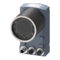
Details the key features, capabilities, and technical attributes of the SIMATIC MV500 optical reader.
Provides instructions and diagrams for the physical installation and initial setup of the SIMATIC MV500.
Explains the elements and information found on the product's nameplate.
Illustrates a typical system setup showing how the optical reader integrates with other components.
Lists the necessary hardware components for the optical reader and its associated PC/PG setup.
Explains the core functionalities of the optical reader, including image acquisition and Web Based Management.
Specifies requirements for personnel operating the device, emphasizing training and authorization for safe operation.
Outlines guidelines for the correct and safe application of Siemens products to ensure proper function.
States that repairs must only be performed by authorized specialists to prevent injury or damage.
Advises on installing only intended system expansions to avoid system damage or warranty invalidation.
Details requirements for connecting the 24 V DC power supply, emphasizing SELV compliance.
Highlights the need for external overvoltage protection for the power supply against electromagnetic pulses.
Provides guidance on protecting the image sensor from damaging radiation sources like lasers or arcs.
Warns about hot surfaces on electrical devices and advises to let them cool before touching.
Explains the capabilities of the optical reader in recognizing and decoding various 1D and 2D barcode types.
Outlines the general applications and provides visual examples of different code types read by the device.
Shows practical examples of two-dimensional codes like Data Matrix, QR, and PDF417 found in applications.
Presents visual examples of various one-dimensional barcodes such as Codabar, Code 128, and EAN.
Details the performance capabilities, tolerances, and operating ranges for reading various types of codes.
Describes the advanced ID-Genius technique for reliable reading of difficult data matrix codes.
Explains the conditions and characteristics for achieving good quality reads of data matrix codes.
Specifies supported QR code dimensions and notes unsupported types like Micro QR and Macro QR.
Details the requirements and unsupported types for reading PDF417 codes effectively.
Outlines the conditions and characteristics for reliable reading of DotCodes.
Provides guidelines and notes for reading various one-dimensional codes, including checksum handling.
Explains the multicode functionality, its limitations, and how to manage multiple code reads.
Describes the process of verifying code quality to ensure readability throughout the product lifecycle.
Introduces the concept of code verification and its importance in ensuring marking quality.
Explains the quality grading system used by the verifier and evaluation levels.
Discusses verification methods tailored for specific applications like printed labels and direct part marks.
Details the AIM and ISO/IEC 16022 standards for verifying printed labels with high contrast.
Covers verification methods for direct part marks (DPM), noting challenges with contrast and standards like ISO/IEC 29158.
Illustrates common defects found in marking quality through visual examples.
Lists the verification standards supported by the optical readers, with and without the Veri-Genius license.
Explains the necessity and procedure for calibrating the reader for accurate verification.
Provides step-by-step instructions for calibrating the optical reader using a calibration plate for optimal results.
Outlines essential requirements for cell size and quiet zones needed for reliable 2D code verification.
Describes how to save and apply a calibration, and how the selected verification standard is applied.
Details specific standards for Data Matrix code verification, including ISO/IEC 16022.
Explains the ISO/IEC 16022 standard, its basis on printing data matrix codes, and its relation to ISO/IEC 15415.
Describes the ISO/IEC 15415 standard for testing 2D symbol print quality, noting unsupported functions.
Details the ISO/IEC 29158 standard for Direct Part Marks, including automatic exposure control and contrast tolerance.
Explains the AS9132 Rev. A standard, focusing on quality criteria for dot peen markings.
Covers Siemens DPM verification, allowing custom quality feature selection for process control.
Explains how to use graphical displays in WBM for troubleshooting marking problems.
Outlines principles similar to data matrix verification but adapted for one-dimensional barcodes.
Describes DotCode quality evaluation based on ISO/IEC 16022, with adaptations for DotCodes.
Explains how to generate and access documentation through verification reports.
Introduces the concept of verification reports as a way to document results.
Details the format of standard test reports, including grades and evaluations for different standards.
Lists output parameters for the ISO/IEC 16022 "Standard" decoder report.
Lists output parameters for the ISO/IEC 15415 standard report.
Lists output parameters for the ISO/IEC 29158 standard report.
Lists output parameters for the AS9132 Rev. A standard report.
Lists output parameters for the Siemens DPM standard report.
Lists output parameters for the ISO/IEC 15416 standard report.
Lists output parameters for the DotCode standard report.
Lists output parameters for the Locator standard report.
Explains PAT Genius, an optical process for identifying and locating objects using models.
Details how PAT Genius object recognition can be integrated and used for creating models in a library.
Highlights key performance aspects of PAT Genius, such as accuracy, invariance, and task handling.
Provides practical examples illustrating object recognition tasks like locating objects and identifying logos.
Describes how to operate object recognition using the "Add locator step" function.
Explains how quality characteristics like Conformity, Match, and Clear percentage provide feedback on recognition reliability.
Covers various methods for controlling image acquisition and processing for different applications.
Explains the "Individual trigger" mode, including image buffering and processing sequences.
Details the "Auto-trigger" mode, which reads codes automatically without external signals.
Describes the "Scan" option suitable for rotating axes, allowing buffered processing of images.
Explains using "Program sequence" mode to evaluate multiple image acquisitions with different settings.
Covers the MATCH command for simple comparisons, its usage, and logging of received match strings.
Provides an overview of system integration options for the optical reader via various communication interfaces.
Illustrates system configurations using PROFINET/PROFIBUS with a communication module (CM).
Describes setting up the reader as a PROFINET IO device using switches, FB 79, or Ident profile.
Details how to set up the system using the Ethernet interface, including PoE power supply.
Explains how to set up the system using the RS-232 interface for communication.
Shows how to integrate the optical reader with an RFID reader using a communication module.
Describes system configuration using a communication module and the auto-trigger function.
Explains system configuration using WinCC flexible or HTML browser for visualization.
Details the connection and configuration for external ring lights.
Briefly mentions other system integration possibilities like Ethernet/IP connections.
Provides essential guidelines for optimal installation, focusing on reading conditions and avoiding interference.
Details the procedure for mounting the reader with built-in ring lights and mini/FF lenses.
Outlines the steps for mounting the reader with built-in ring lights and EF lenses.
Describes the available attachments for built-in ring lights, such as polarization filters and anti-glare options.
Explains how to mount and connect an external ring light for applications requiring more illumination.
Provides guidance on shielding and grounding to prevent electrical interference during installation.
Details the use of Power over Ethernet (PoE) for powering network components via Ethernet cables.
Covers the procedures for connecting the reader, including power supply options and interface details.
Explains permissible power supplies (SELV, LPS) and protection against external power supply interference.
Illustrates the physical interfaces and connection sockets available on the SIMATIC MV550.
Provides pin assignments for Power-IO RS232 and communication module cables.
Details the pin assignment and functionality of the Power IO RS232 cable for power and data.
Describes the communication module cable, its pin assignment, and power supply options.
Explains the industrial Ethernet connecting cables and their pin assignments for different interfaces.
Provides practical wiring examples for I/O interfaces and Power IO RS232 connections.
Shows wiring diagrams for I/O interfaces configured as P type and N type.
Illustrates wiring connections for the Power IO RS232 interface in P and N types.
Details how to connect external ring lights and floodlights, including wiring diagrams.
Explains connecting external ring lights using the "Strobe" output signal and provides wiring diagrams.
Details wiring for external floodlights, including brightness control options.
Lists the PC requirements and network connection needed for device commissioning.
Describes the quick connection method using the "CONNECT" button to access WBM.
Explains the automatic adaptation process using the "READ" button or "Full program" for optimal settings.
Provides a step-by-step guide for connecting, setting up, and configuring the reader via Ethernet and WBM.
Details connecting the reader directly to a PC using an Ethernet cable.
Instructs on switching on the power supply and notes the self-test procedure.
Guides through configuring the Ethernet connection, assigning IP addresses, and setting PROFINET names.
Explains how to start the Web Based Management interface to configure and operate the reader.
Details aligning the optical reader using the "Auto-setup" function for optimal image focus and positioning.
Describes the process of installing and transferring optional licenses for extended functionality.
Outlines the procedure for installing the Automation License Manager and the MV plug-in.
Explains how to remove a license if it is no longer required.
Discusses different operating modes and network configurations for connecting the reader.
Explains how to start the Web Based Management (WBM) for reader setup and control.
Provides an overview of the WBM interface, including status bar, menu tree, and main window.
Describes the components of the WBM status bar and toolbar, including reader status and access status.
Details the different reader statuses (Start, Stop, Edit, Adapt) and access statuses (padlocks).
Explains the login area for user management and accessing WBM with appropriate permissions.
Mentions accessing context-sensitive online help within the WBM using the "?" symbol.
Describes the main window content and its division into columns for parameter configuration.
Explains the message area for displaying WBM-related error messages and warnings.
Refers to alternative user interfaces for reader operation.
Covers WBM login procedures when the reader is controlled by an automation system (DISA active).
Explains the role of the DISA bit in ensuring automation system control and limiting user access.
Details integrating the reader into automation systems via PROFINET IO without a communication module.
Explains how to integrate the reader into controllers using the provided GSD file.
Guides on assigning unique PROFINET device names for reader identification in the network.
Describes integrating the reader into control systems using communication modules (CM).
Details configuration with FB 79 or Ident profile, selecting the required function block.
Explains process connection and control using the Ident profile and related function blocks.
Describes assigning parameters to the Ident profile and the required function modules in STEP 7.
Details controlling the reader using "PHYSICAL WRITE" and "PHYSICAL READ" commands via the Ident profile.
Explains how status bits indicate the reader's operating state and error conditions.
Covers the initialization process with or without program selection for reader startup.
Details the "PHYSICAL WRITE" command for sending MV commands and managing reader settings.
Explains the "PHYSICAL READ" command for retrieving data, results, and status from the reader.
Describes how to interpret command processing results via the "STATUS" output.
Lists the necessary preconditions for executing various commands to ensure successful operation.
Explains how to identify and acknowledge group errors, and the initialization procedures.
Details controlling the optical reader using function block FB 79 for PROFINET IO operations.
Maps control and status bytes to PROFINET IO interfaces for reader control.
Explains how to use the control/status byte to select operating modes like program selection and saving.
Provides a sample STL program for data exchange with specific S7 controllers.
Introduces handshaking procedures to ensure data consistency during transfer from the reader.
Describes the function block FB 79 for PROFINET IO operations and its functional scope.
Provides a detailed overview of the parameters for the FB 79 function block.
Explains how job execution depends on the reader's operating state and provides sequences for job management.
Details how to interpret error codes and warnings from FB 79 and the optical reader.
Explains how to control the reader using digital inputs and outputs, depending on WBM settings.
Describes controlling the reader using TCP/IP or RS232 connections, including command strings.
Explains how character strings trigger image acquisition and processing.
Details writing match strings to overwrite program settings, noting that changes are not persistent.
Explains commands for setting and resetting the DISA bit to manage reader control.
Describes the "MGST" command to query the reader's status, program number, and error information.
Explains how to change the program or switch processing mode using the "MR" command.
Details saving programs using an internal trigger, noting overwriting behavior and requirements.
Explains saving programs with an external trigger, requiring prior DISA bit setting.
Describes the "MRES" command for acknowledging errors or canceling save procedures.
Explains how to set logic signals for digital outputs via commands or WBM.
Explains implementing scanner portal applications using multiple optical readers for an extended field of view.
Details the WBM configuration steps for master and slave devices in a scanner portal setup.
Describes how the master device synchronizes and outputs read results from slave devices.
Introduces the remote client interface for triggering functions via HTTP requests and managing backups.
Explains XML backup and restore functions, noting potential impact on diagnostic images and security.
Details the HTTP request and response structure for performing an XML backup.
Covers the process for restoring settings and programs from an XML backup file.
Introduces Simple Network Management Protocol (SNMP) for managing networks and devices.
Presents example programs for connecting the reader to SIMATIC controllers and archiving data.
Provides a guide for connecting the reader to a SIMATIC controller using FB 79.
Describes using the MMI Diagnostic Recorder to save diagnostic data and images to a PC.
Explains how to access and interpret diagnostic information, including error messages and warnings.
Classifies messages into error messages, warnings/notes, and read results displayed in WBM.
Lists common error messages, their descriptions, and corrective measures for troubleshooting.
Details specific error outputs related to read results, including filter and match errors.
Provides a comprehensive list of read and verification error codes and their descriptions.
Lists error messages related to filter configurations and symbol content validation.
Explains the meaning of LED indicators (PWR, ER, R/S, LK, CONNECT, READ) for device status.
Describes potential errors displayed by the READ LED during automatic adaptation.
Explains how to read out I/O device diagnostic information using STEP 7 and PROFINET IO.
Details reading diagnostic information via OB82 and interpreting local variables for errors.
Explains retrieving PROFINET IO diagnostics using SFB 54 "RALRM".
Lists errors that can occur during automatic data backup, such as missing microSD cards or insufficient space.
Covers maintenance procedures, cleaning recommendations, and guidelines for sending the device for repair.
States devices are maintenance-free, but recommends professional cleaning for the protective lens barrel.
Provides instructions for sending the reader for repair to Siemens, excluding certain components.
Explains how to restore the reader's configuration to factory default settings using WBM, manual buttons, or SINEC PNI.
Details the procedure for resetting all settings to factory defaults using the Web Based Management interface.
Describes the manual procedure using the READ and CONNECT buttons to reset the reader to factory settings.
Explains how to restore Ethernet interface settings to factory defaults using SINEC PNI.
Covers procedures for replacing modules, including backing up configurations and ensuring compatibility.
Emphasizes backing up the reader's configuration before module replacement for easy transfer.
Outlines the step-by-step process for exchanging a reader, including connection and configuration loading.
Provides detailed technical specifications for the SIMATIC MV500 optical reader and its variants.
Lists the types of 1D and 2D codes supported by the SIMATIC MV500 optical reader.
Details the available interfaces, including combination, Ethernet, and digital I/O.
Specifies the design of the image sensor/camera for different device versions (S, H, U, X).
States the image capture method (global shutter) and operating distance for lenses.
Provides operating distances for mini lenses and EF lenses.
Specifies the lens mounting type as C-mount.
Lists available light sources: built-in ring lights or external ring lights.
Lists the maximum image acquisition frequencies for different device versions (S, H, U, X).
Describes focusing methods for mini-lenses (manual) and EF lenses (automatic).
Details the supply voltage, typical and maximum current consumption, and power loss.
Provides details on the housing material and color.
Specifies the permitted ambient temperatures for operation, transportation, and storage.
States the degree of protection (IP67) according to IEC 60529.
Lists the shock resistance rating (IEC 60068-2) and acceleration value.
Provides the vibration acceleration specification.
Lists the technical specifications for various EF lenses, including aperture, focus, and dimensions.
Provides technical specifications for the built-in ring lights, including lighting distance, color, and flash mode.
Details technical specifications for external ring lights, including lighting distance, color, flash mode, and power.
Lists technical specifications for external floodlights, including lighting distance, irradiance, and power.
Shows dimension drawings of the SIMATIC MV500 optical readers.
Provides dimension drawings for protective lens barrels for the MV500 series.
Shows dimension drawings for protective lens barrel extensions of different lengths.
Includes dimension drawings for the mounting plate used with SIMATIC MV500.
Displays dimension drawings of the SIMATIC MV500 with an external ring light and mounting plate.
Shows dimension drawings for the external ring light.
Provides dimension drawings for the ring light holder for external ring lights.
Provides an overview of the SIMATIC MV500 product range, including readers and accessories.
Lists the categories of products within the SIMATIC MV500 range, including readers and accessories.
Lists the different SIMATIC MV500 optical reader models with their descriptions and article numbers.
Guides on selecting appropriate components based on ambient conditions and reading requirements.
Notes partial compatibility of MV440 accessories with MV500 readers.
Lists available accessories for the SIMATIC MV500, categorized by type.
Details various mini-lenses and EF lenses, including their specifications and article numbers.
Lists built-in ring lights for SIMATIC MV500 with their descriptions and article numbers.
Details external ring lights and floodlights, including power supply, light source, and dimensions.
Lists protective lens barrels compatible with lenses and ring lights, noting extensions and variations.
Lists suitable PoE switches for powering SIMATIC MV500 readers via Ethernet.
Provides ordering information for industrial Ethernet cables, connectors, and other accessories.
Lists mounting plates and the calibration card with their specifications and article numbers.
Guides on selecting appropriate components like lenses and ring lights based on operating conditions and requirements.
Lists CE mark, ISO 9001 certification, EMC Directive, and country-specific approvals.
Details the CE mark, ISO 9001 certification, and EMC Directive compliance.
Provides essential guidelines for handling electrostatic sensitive devices (ESDs) to prevent damage.
Discusses alternative user interfaces, including user-defined interfaces and integrated HTML pages.
Explains creating custom user interfaces using Web API communication and adapting HTML pages.
Highlights the benefits of integrated HTML pages for obtaining information and monitoring processes.
Describes using saved images from a PC for parameter assignment or trial mode with HTML5 browsers.
Directs users to Siemens Industry Online Support for manuals, FAQs, and technical forums.
Provides a link to the Siemens homepage for general information on identification systems.
Points to the Siemens Industry Mall for online catalogs and ordering.
Offers information on SITRAIN training courses for various sectors and locations.
| Model | SIMATIC MV500 |
|---|---|
| Sensor Type | CMOS |
| Operating Voltage | 24 V DC |
| Frame Rate | Up to 60 fps |
| Operating System | Linux-based |
| Connectivity | Gigabit Ethernet |
| Power Supply | 24 V DC |
| Operating Temperature | 0°C to 50°C |