Network and system integration
4.2 System configuration via PROFINET/PROFIBUS with CM
SIMATIC MV500
94 Operating Instructions, 03/2021, C79000-G8976-C494-05
Simultaneous use of both Ethernet interfaces with MV550/MV560
Note that both Ethernet interfaces "X1 LAN1" and "X2 LAN2" must be connected to
physically separated networks if you want to use both interfaces at the same time. A purely
logical separation using different subnets is not sufficient and can cause network problems
4.2 System configuration via PROFINET/PROFIBUS with CM
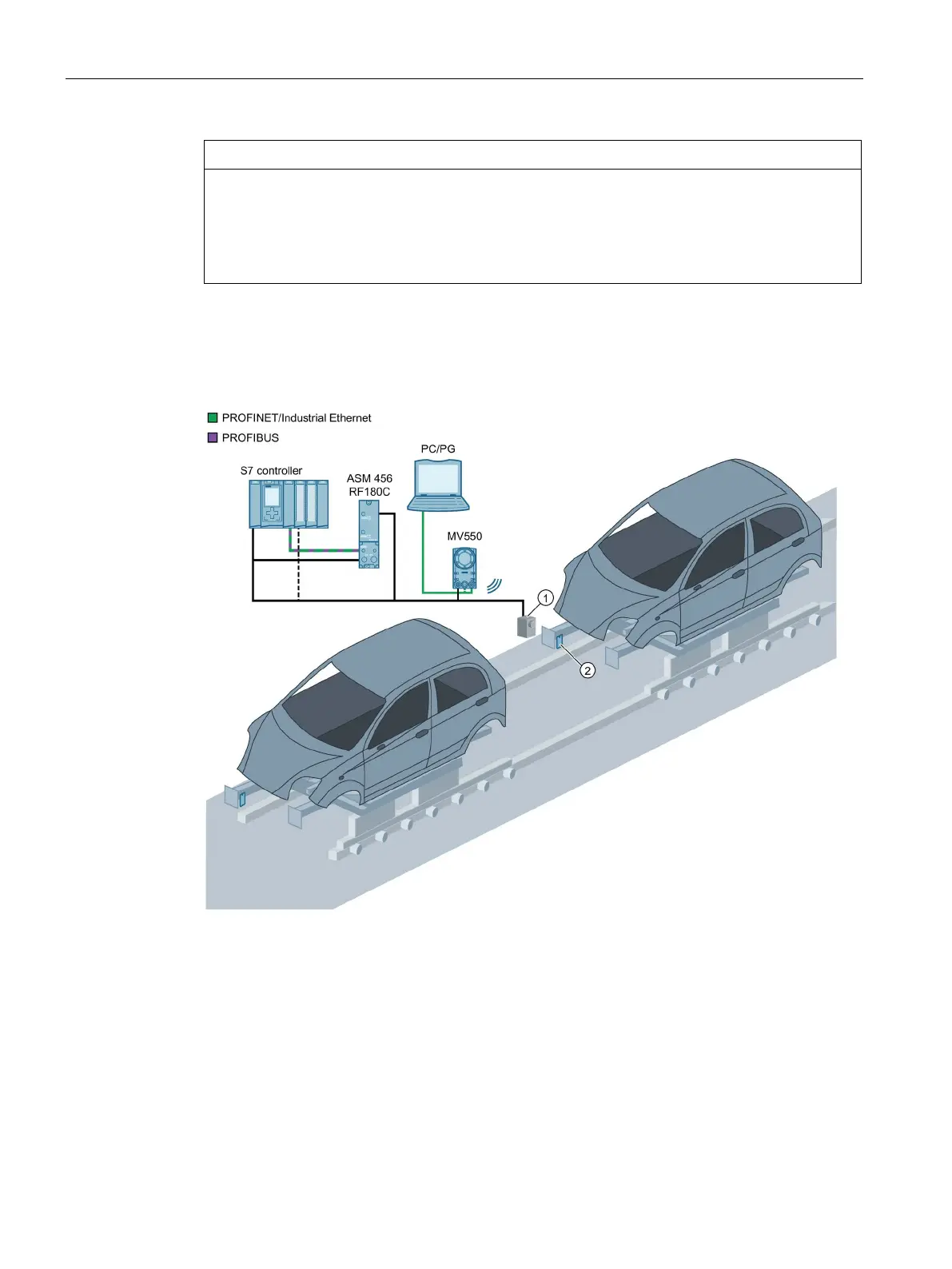
Optical sensor or light barrier (for trigger signal)
Figure 4-1 Example: System configuration via PROFINET IO/PROFIBUS DP-V1 with communication
module
System characteristics
• The PROFINET/PROFIBUS connection is made via the CM interface of the optical reader and
a communication module.
• PROFINET IO/PROFIBUS DP-V1 is connected to an S7 controller.