Network and system integration
4.5 System setup via the RS-232 interface
SIMATIC MV500
98 Operating Instructions, 03/2021, C79000-G8976-C494-05
4.5 System setup via the RS-232 interface
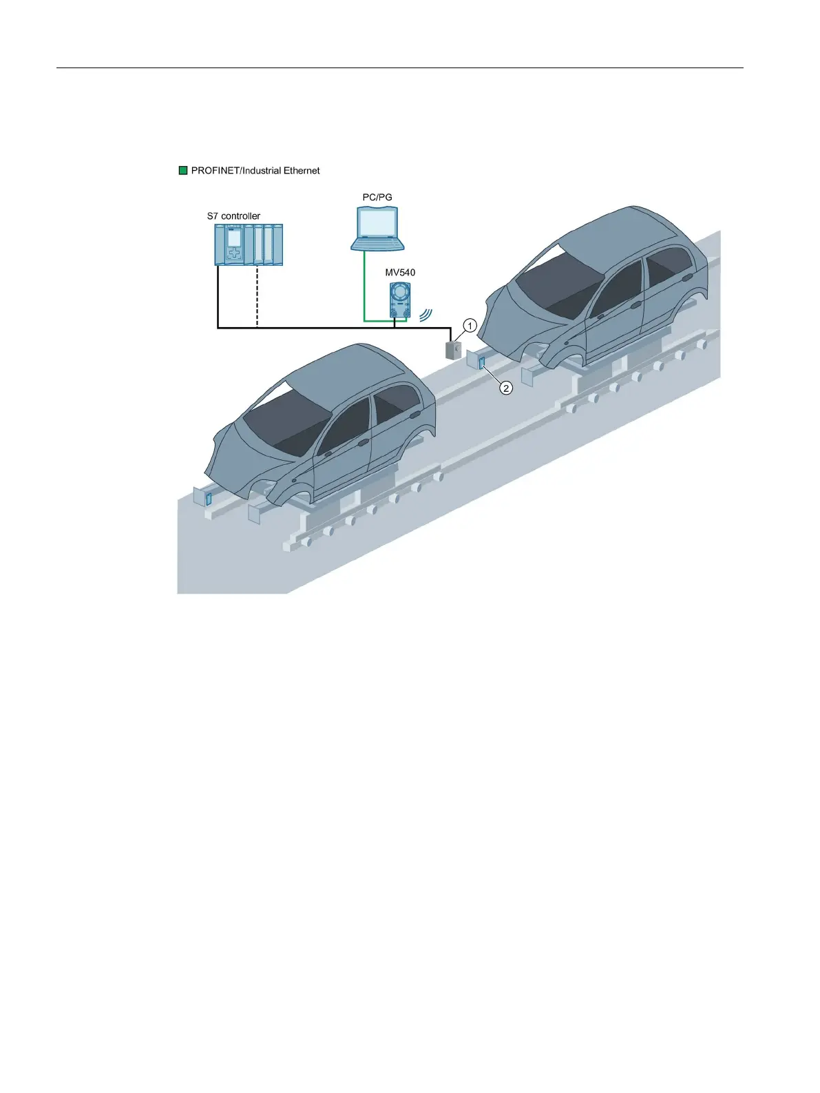
Optical sensor or light barrier (for trigger signal)
Figure 4-4 Example: System configuration via the RS232 interface
System characteristics
• The results of the optical reader are output to the controller via the RS232 interface.
• The optical reader is triggered either via digital I/O, RS232 or via the built-in auto-trigger
function.
• A PC/programming device is connected via Ethernet for the adjustment procedure.