Passive Components for RS-485 Networks
4-38
PROFIBUS Networks SIMATIC NET
6GK1970-5CA20-0AA1 Release 2 05/2000
Connecting Up the LAN Cable
Connect up the LAN cable to the bus connector with order number
6ES7 972-0B.11 ... as follows:
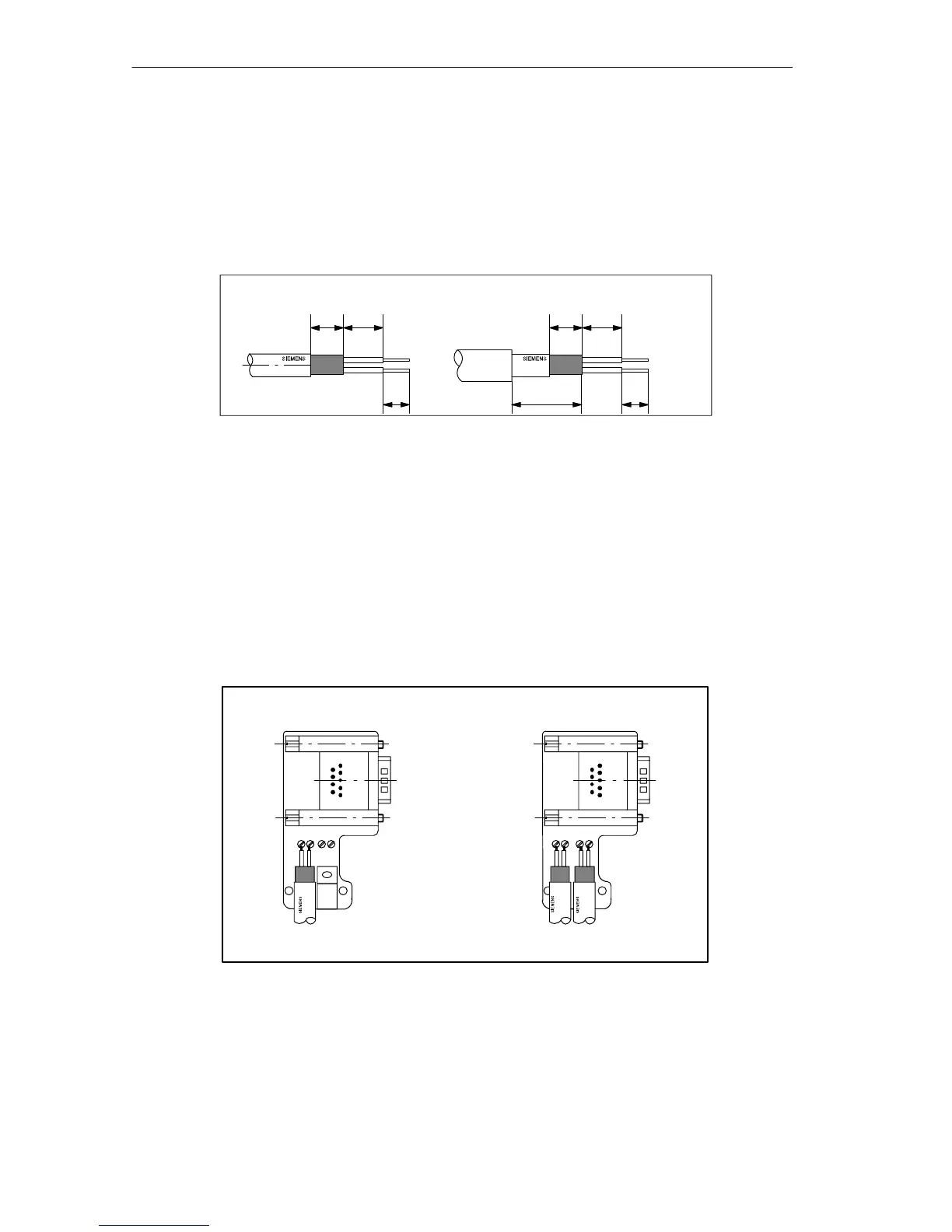
1. Strip the LAN cable as shown in Figure 4-16 using the FastConnect stripping
tool (sizes and lengths are shown in the table on the rear of the tool).
7.5 9
6
7.5 9
6
6XV1 830-0EH10 6XV1 830-3FH10
16
Figure 4-16 Cable Stripped for Connection to Bus Connector (6ES7 972-0B.11 ...)
2. Open the casing of the bus connector by undoing the screws and removing the
cover.
3. Insert the green and red cores in the screw terminal as shown in Figure 4-17.
Make sure that you always connect the same cores to the same terminal A or B
(for example terminal A is always connected to green and terminal B always to
red).
4. Press the cable sheath between the two clips. This secures the cable.
5. Screw the green and red cores tight in the screw terminal.
A B A B A B A B
LAN cable attachment for
first and last station on the
bus
1
LAN cable attachment for all
further stations on the bus
1
: The LAN cable must always be connected up on the left-hand side.
Figure 4-17 Connecting the LAN Cable to the Bus Connector (6ES7 972-0B.11 ...)
6. Fasten the cover again with the screws.
Make sure that the cable shield makes good contact with the shield clamp.