Passive Components for RS-485 Networks
4-58
PROFIBUS Networks SIMATIC NET
6GK1970-5CA20-0AA1 Release 2 05/2000
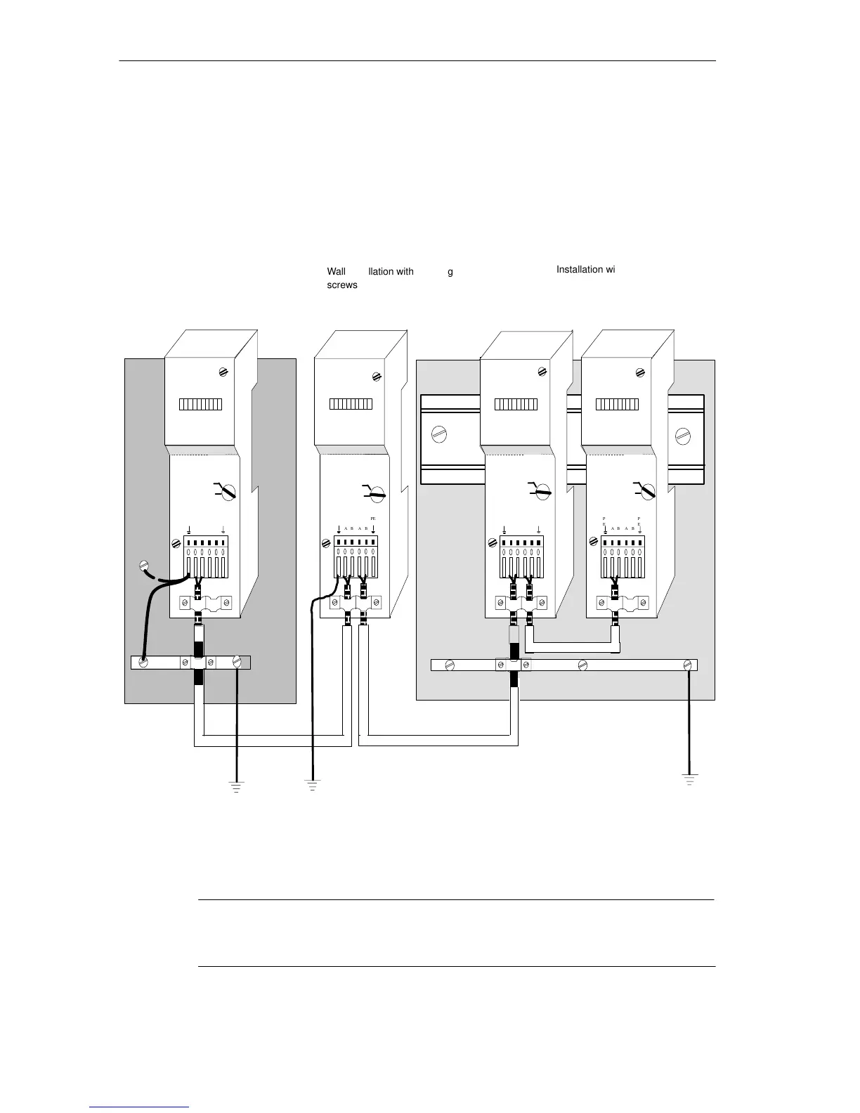
4.7.5 Grounding
If the bus terminal is mounted on a DIN rail (see Figure 4-33), the shield clamp
makes large-area contact with the rail via an internal spring. To connect the cable
shield with local ground, a connection between the DIN rail over as short a
distance as possible to local earth is adequate.
PE
AB AB
PE
P
E
AB A B
P
E
AB AB
PE
PE
AB AB
PE
Wall installation with securing
screws
Installation with a standard rail
on a cabinet panel
Shield clamp/
PE
grounding bar
Installation on closet panel
with securing screws
Bus
terminated
Bus
terminated
Bus
terminated
Bus
terminated
Shield clamp/
grounding bar
MADE IN GERMANY
MADE IN GERMANY
MADE IN GERMANY
MADE IN GERMANY
1)
2
)
1) If this grounding cable exceeds a length of 20 cm,
the shield must be grounded to the closet panel (2).
Figure 4-33 Ways of Installing and Grounding the Bus Terminal
Note
The grounding bar and local ground must be connected by a Cu conductor with ≥
6 mm
2
cross-section over as short a distance as possible.