Passive Components for RS-485 Networks
4-49
PROFIBUS Networks SIMATIC NET
6GK1970-5CA20-0AA1 Release 2 05/2000
4.7.2 Design and Functions of the RS-485 Bus Terminal
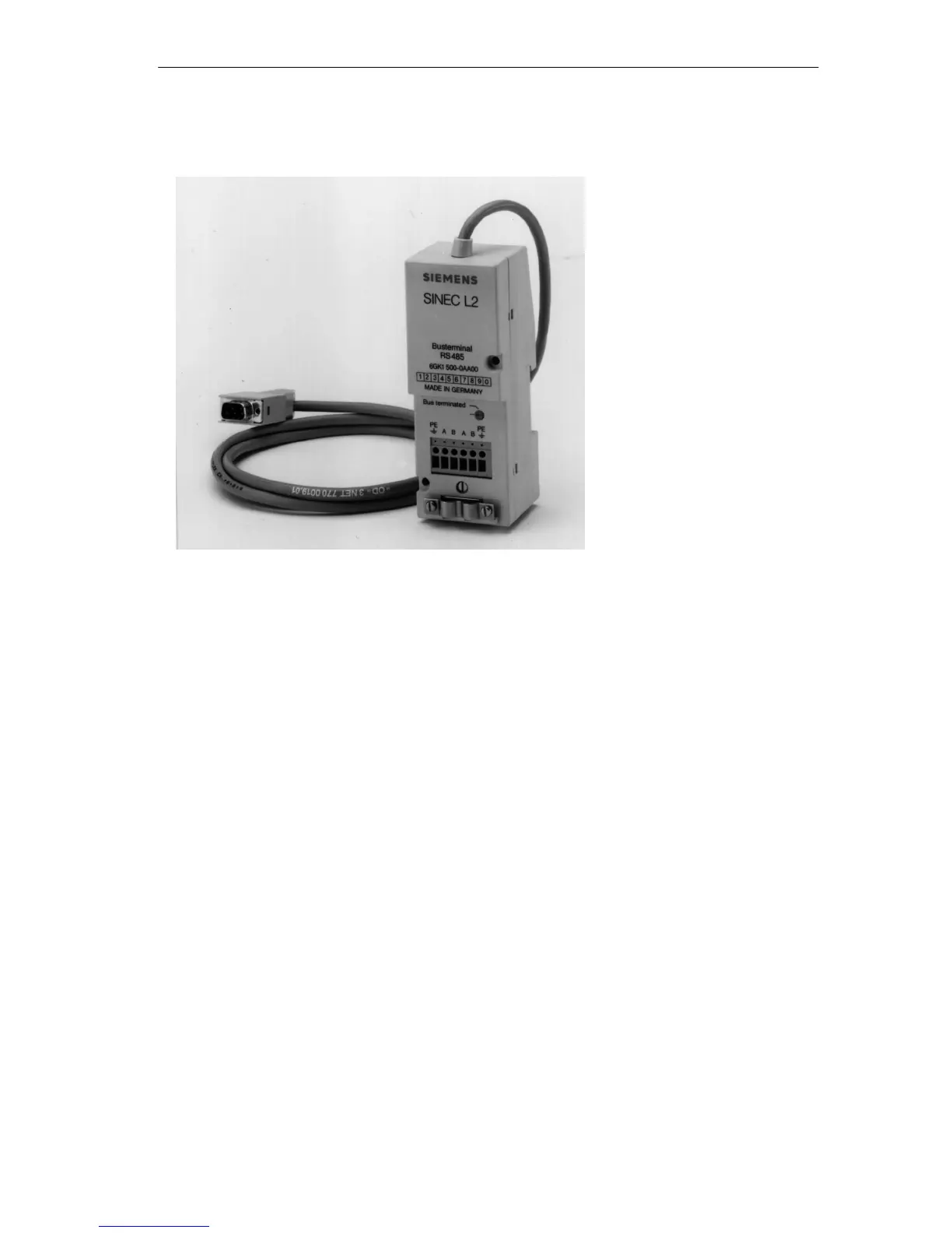
Figure 4-27 RS-485 Bus Terminal
Bus Terminal RS-485
The RS-485 bus terminal is used to connect data terminal equipment (DTEs) with
an RS-485 interface to the LAN cable. It includes the following:
S 6 modular terminals for conductors with a cross-sectional area ≤ 1.5 mm
2
for
connection of the incoming and outgoing LAN cable and, if necessary, the
protective earth (PE)
S Screw down clamps for shield contact
S A switch (“Bus terminated”) to allow termination at the end of an RS-485
segment with the characteristic impedance
S A connecting cable preassembled (either 1.5 m or 3 m long) with a 9-pin sub-D
male connector for direct connection to a DTE.
Cable Termination
The sub-D connector is plugged into the sub-D female connector of the DTE and
secured by screws. If the terminating resistor is activated, the RS-485 bus terminal
requires current of maximum 5 mA at a power supply of 5 V between pins 5 and 6
of the connector from the DTE.