Passive Components for RS-485 Networks
4-55
PROFIBUS Networks SIMATIC NET
6GK1970-5CA20-0AA1 Release 2 05/2000
4.7.4 Mounting/Attaching the LAN Cables
The bus terminal can be mounted in three different ways:
S By snapping it on to a 15 x 35 mm standard DIN rail (DIN EN50022-35x15)
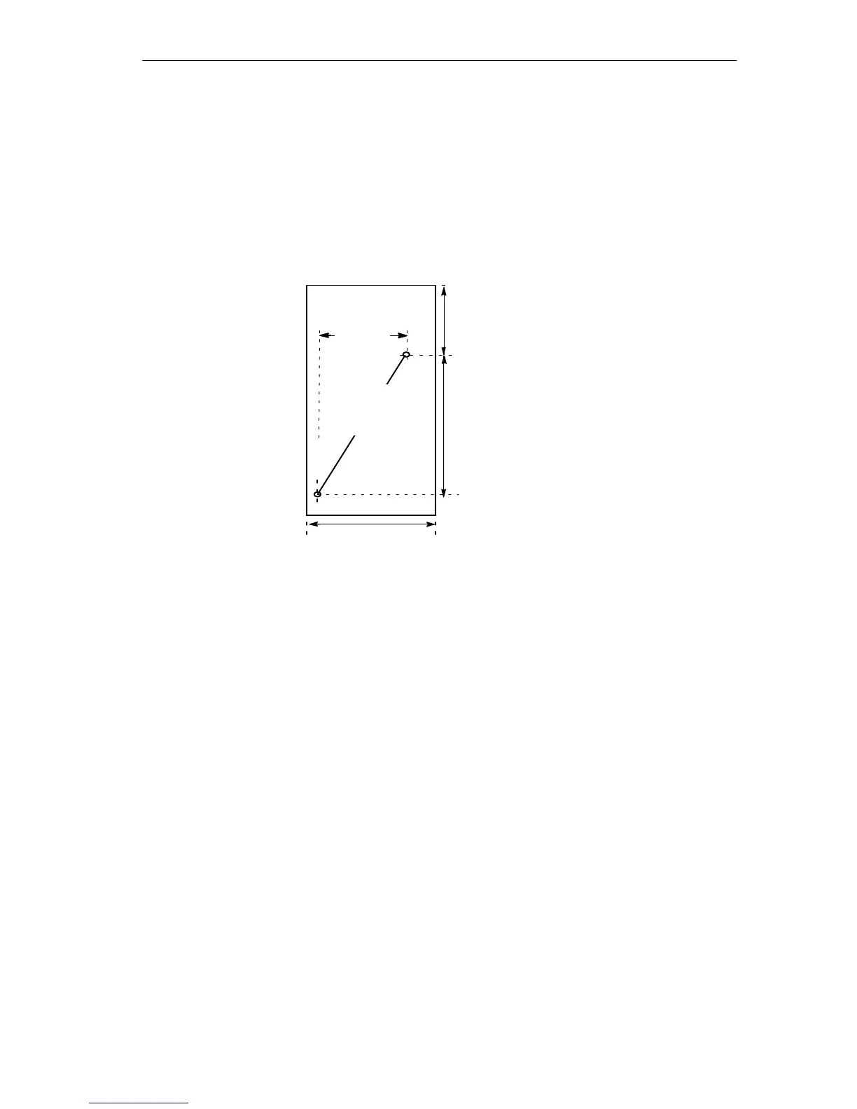
S By screwing the unit to a mounting plate using two fillister head screws. Figure
4-31 shows the drilling diagram for mounting the unit.
Thread M4 or
through-hole
4.2 mm
42.5 mm
50 mm
67.3 mm
50 mm
Top edge of bus terminal
Figure 4-31 Drilling Diagram for the Bus Terminal
S Wall mounting (brick, concrete). Fittings required: 2 x 5 mm plugs,
2 round head wood screws size 3.5 mm and 2 washers 4.3 mm inner diameter.
The holes must be drilled as shown in Figure 4-31.