Passive Components for RS-485 Networks
4-46
PROFIBUS Networks SIMATIC NET
6GK1970-5CA20-0AA1 Release 2 05/2000
4.6 Plugging the Bus Connector into the Module
Fitting the Bus Connector
To fit the bus connector, follow the steps outlined below:
1. Plug the bus connector into the module.
2. Screw the bus connector to the module.
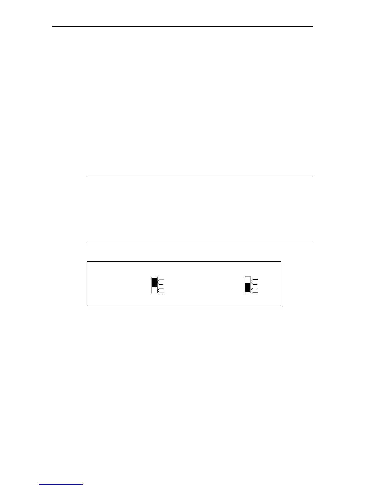
3. If the bus connector is located at the start or end of a segment, you must
activate the terminating resistor (switch setting ON”) (see Figure 4-26).
It is not possible to activate the terminating resistor on the bus connector
6ES7 972-0BA30-0XA0.
Note
Remember the following:
S By activating the terminating resistor, the outgoing LAN cable is
disconnected from the incoming LAN cable.
S Stations equipped with a terminating resistor must always be
supplied with voltage when the network starts up and during
operation.
Terminating
resistor activated
Terminating resistor
not activated
on
off
on
off
Figure 4-26 Bus Connector (6ES7 972-0B.11-...): Terminating Resistor Activated and
deactivated
Removing the Bus Connector
If the LAN cable is connected through, you can remove the bus connector from
the PROFIBUS-DP interface at any time without interrupting data traffic on the
bus.