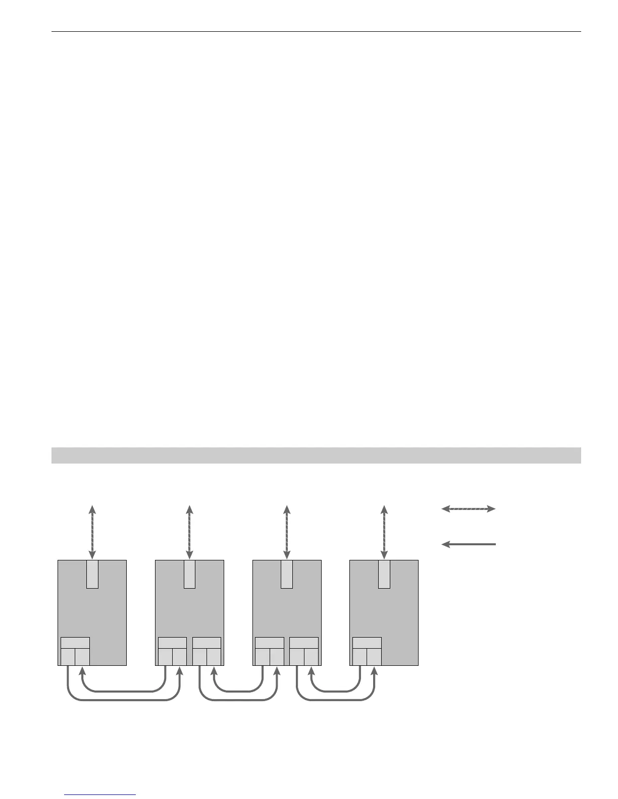
3.1 Line topology
9
3 Network Topologies
Version 1.0 8/00
3 Network Topologies
The following network topologies can be realized with the PROFIBUS OLM:
Point-to-point connections
Line topologies
Star topologies
Redundant optical rings
Combinations of these basic types are also possible. Lines with two optical fibers are used to create the fiber links for
these network topologies.
If a malfunction – e.g. a break in a fiber line – makes a high degree of field bus network fail-safety necessary, the
availability of the network can be increased using a redundant network configuration.
Please note:
Single terminals or entire PROFIBUS segments with max. 31 subscribers can be connected to the electrical
interface of the PROFIBUS OLM.
In areas with a high EMC incidence, only lay optical fiber lines in order to exclude the possibility of EMC
affecting the whole network.
Optically only OLMs of the same type can be connected together:
– OLM/P11 with OLM/P12
– OLM/G11 with OLM/G12 and OLM/G12 EEC
– OLM/G11-1300 with OLM/G12-1300
Optical ports which are connected by optical fiber must be set to the same operating mode.
Junctions between different OLM types are only possible via the RS485 interface.
OLM/G12-EEC can be used everywhere in those network topologies described below in which a OLM/G12 can
also be used.
3.1 Line topology
Fig. 2: Network structure in an optical line topology