Passive Components for RS-485 Networks
4-42
PROFIBUS Networks SIMATIC NET
6GK1970-5CA20-0AA1 Release 2 05/2000
4.4.3 Connecting the LAN Cable to Bus Connector (6ES7 972-0B.40)
Appearance (6ES7 972-0B.40 ...)
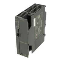
Figure 4-21 shows the bus connector with order number 6ES7 972-0B.40 ...
Screws for
mounting on the
station
9-pin sub-D male
connector for
connection to the
station
Housing screws
PG socket (only with
6ES7
972-0BB40-0XA0)
Figure 4-21 Bus Connector (order number 6ES7 972-0B.40 ...)
Connecting Up the LAN Cable
Connect up the LAN cable to the bus connector with order number
6ES7 972-0B.40 ... as follows:
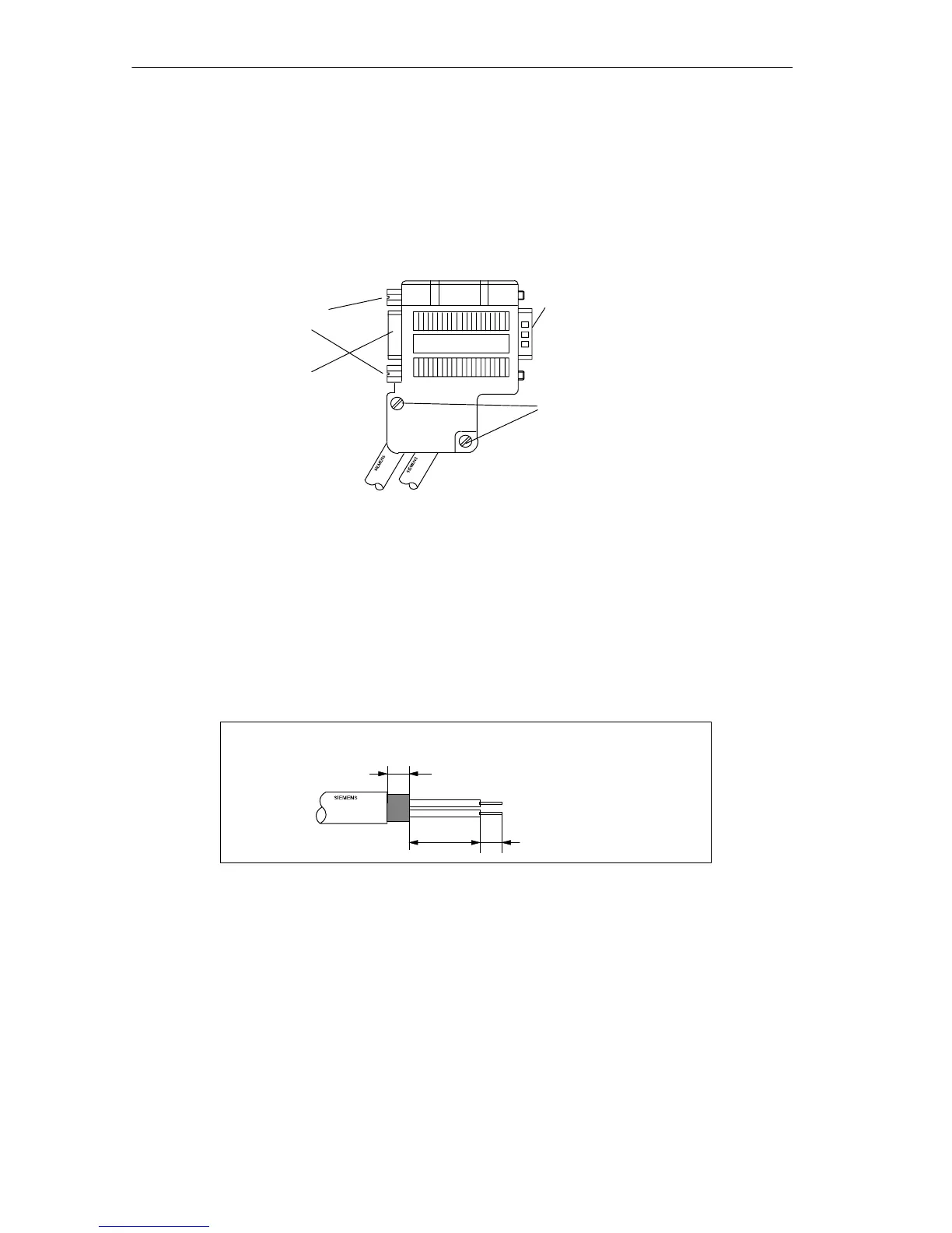
1. Strip the LAN cable as shown in Figure 4-22 using the FastConnect stripping
tool (sizes and lengths are shown in the table on the rear of the tool).
6XV1 830-0EH10
A1 B1
7.5
516
Figure 4-22 Cable Stripped for Connection to Bus Connector (6ES7 972-0B.40 ...)
2. Open the casing of the bus connector by undoing the screws and removing the
cover.
3. Insert the green and red cores in the screw terminal as shown in Figure 4-22.
Make sure that you always connect the same cores to the same terminal A or B
(for example terminal A is always connected to green and terminal B always to
red).
4. Press the cable sheath between the two clips. This secures the cable.