Passive Components for RS-485 Networks
4-41
PROFIBUS Networks SIMATIC NET
6GK1970-5CA20-0AA1 Release 2 05/2000
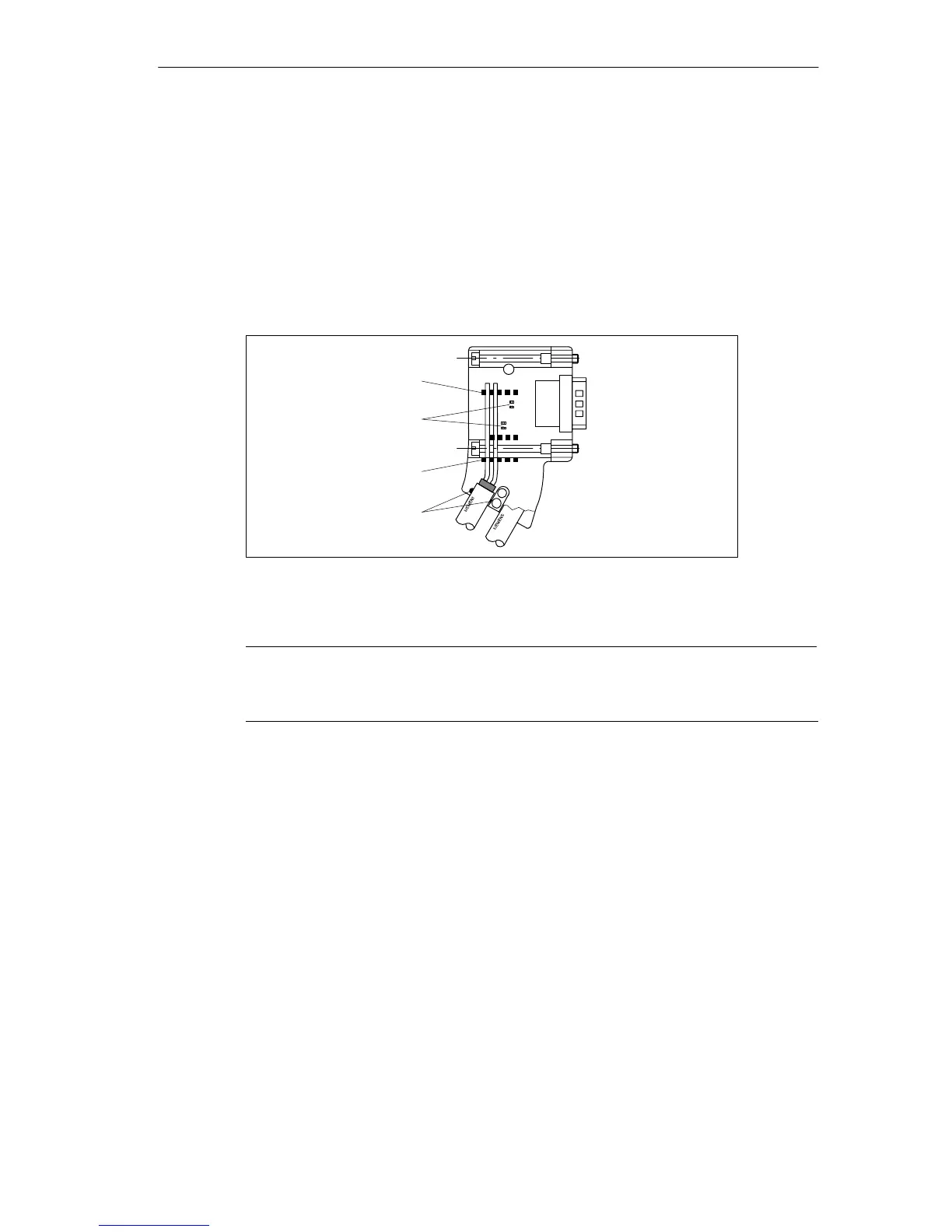
4. Place the green and red cores in the cable guides above the insulation
displacement terminals as shown in Figure 4-20.
Make sure that you always connect the same cores to the same terminal A or B
(for example terminal A is always connected to green and terminal B always to
red).
5. Press the red and green cores into the insulation displacement terminals lightly
using your thumbs.
6. Secure the cover with the screws.
A BA B
Cable guides
Strain relief
Cable guides
Insulation
displacement
terminals
Figure 4-20 Connecting the LAN cable to bus connector (6ES7 972-0BA30-0XA0)
Note
The bus connector 6ES7 972-0BA30-0XA0 cannot be fitted to LAN cables with
stranded cores.