Passive Components for RS-485 Networks
4-40
PROFIBUS Networks SIMATIC NET
6GK1970-5CA20-0AA1 Release 2 05/2000
4.4.2 Connecting the LAN Cable to Bus Connector (6ES7
972-0BA30-0XA0)
Appearance (6ES7 972-0BA30-0XA0)
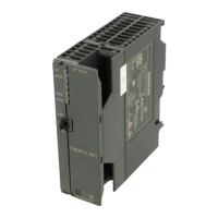
Figure 4-18 shows the bus connector with order number 6ES7 972-0BA30-0XA0:
Screws for
mounting on the
station
9-pin sub-D male
connector for
connection to the
station
Casing screws
Figure 4-18 Bus Connector (order number 6ES7 972-0BA30-0XA0)
Connecting Up the LAN Cable
Connect up the LAN cable to the bus connector with order number
6ES7 972-0BA30-0XA0 as follows:
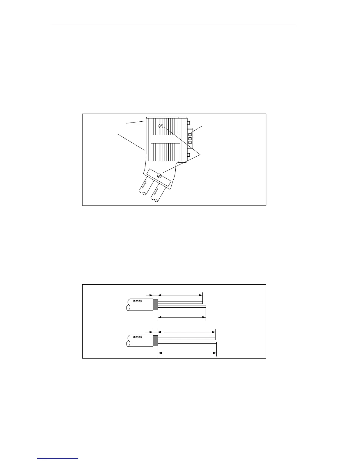
1. Strip the insulation as shown in Figure 4-19.
3
3
A
B
A
B
27
35
29
36
Figure 4-19 Cable Stripped for Connection to Bus Connector (6ES7 972-0BA30-0XA0)
2. Open the casing of the bus connector by undoing the screws and removing the
cover.
3. Press the LAN cable into the strain relief clips. The cable shield must make
good contact with the metal part.