Passive Components for RS-485 Networks
4-43
PROFIBUS Networks SIMATIC NET
6GK1970-5CA20-0AA1 Release 2 05/2000
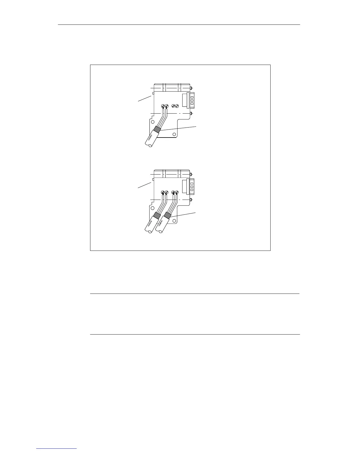
5. Screw the green and red cores tight in the screw terminal.
LAN cable attachment for
first and last station on the
bus
1
LAN cable attachment for all
further stations on the bus
1
: The LAN cable must always be connected up on the left-hand side.
A B A B
A B
A B
Switch = “ON”
(terminating resistor
activated)
Switch = “OFF”
(terminating resistor
deactivated)
Cable shield must make
good contact with the metal
part.
Cable shield must make
good contact with the metal
part.
Figure 4-23 Connecting the LAN Cable to Bus Connector (6ES7 972-0B.40 ...)
6. Fasten the cover again with the screws.
Note
Stranded cores must only be used in screw terminals with wire-end ferrules fitted
(0.25 mm
2
complying with DIN 46228). Use only wire-end ferrules made of
materials with permanently stable contact properties, for example copper with a
tin-plated surface (not aluminum).