Passive Components for RS-485 Networks
4-45
PROFIBUS Networks SIMATIC NET
6GK1970-5CA20-0AA1 Release 2 05/2000
Fitting the Bus Connector
Points to note about installing the bus connector with axial cable outlet (order
number 6GK1 500-0EA02):
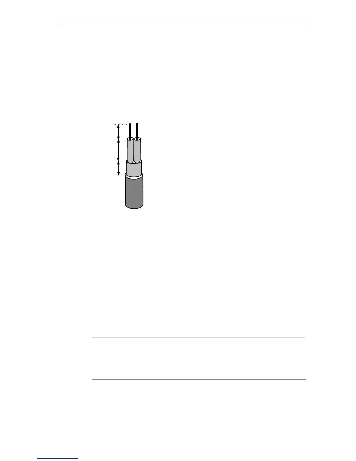
S Strip both cable ends as shown in Figure 4-25 with the FastConnect stripping
tool (sizes and lengths are shown in the table on the rear of the tool).
10 mm
7.5 mm
AB
approx. 6 mm
Figure 4-25 Preparing the Ends of the Cable for the Bus Connector with Axial Cable Outlet
S Undo the screws in the casing and remove the cover.
S Feed the wires into the required terminals of the screw terminal blocks.
S Press the cable sheath between the two clips.
S Make sure that the cable sheaths are lying on the metal conductor.
S When you connect to the screw terminals, the stranded cores must be fitted
with wire-end ferrules (0.25 mm
2
complying with DIN 46228).
S Make sure that the braid shield lies on the contact surfaces of the connector.
S Replace the cover and screw it tight.
S Activate the terminating resistor if the bus connector is at the end of a segment.
Note
Stranded cores must only be used in screw terminals with wire-end ferrules fitted
(0.25 mm
2
complying with DIN 46228). Use only wire-end ferrules made of
materials with permanently stable contact properties, for example copper with a
tin-plated surface (not aluminum).