Active Components for RS-485 Networks
5-3
PROFIBUS Networks SIMATIC NET
6GK1970-5CA20-0AA1 Release 2 05/2000
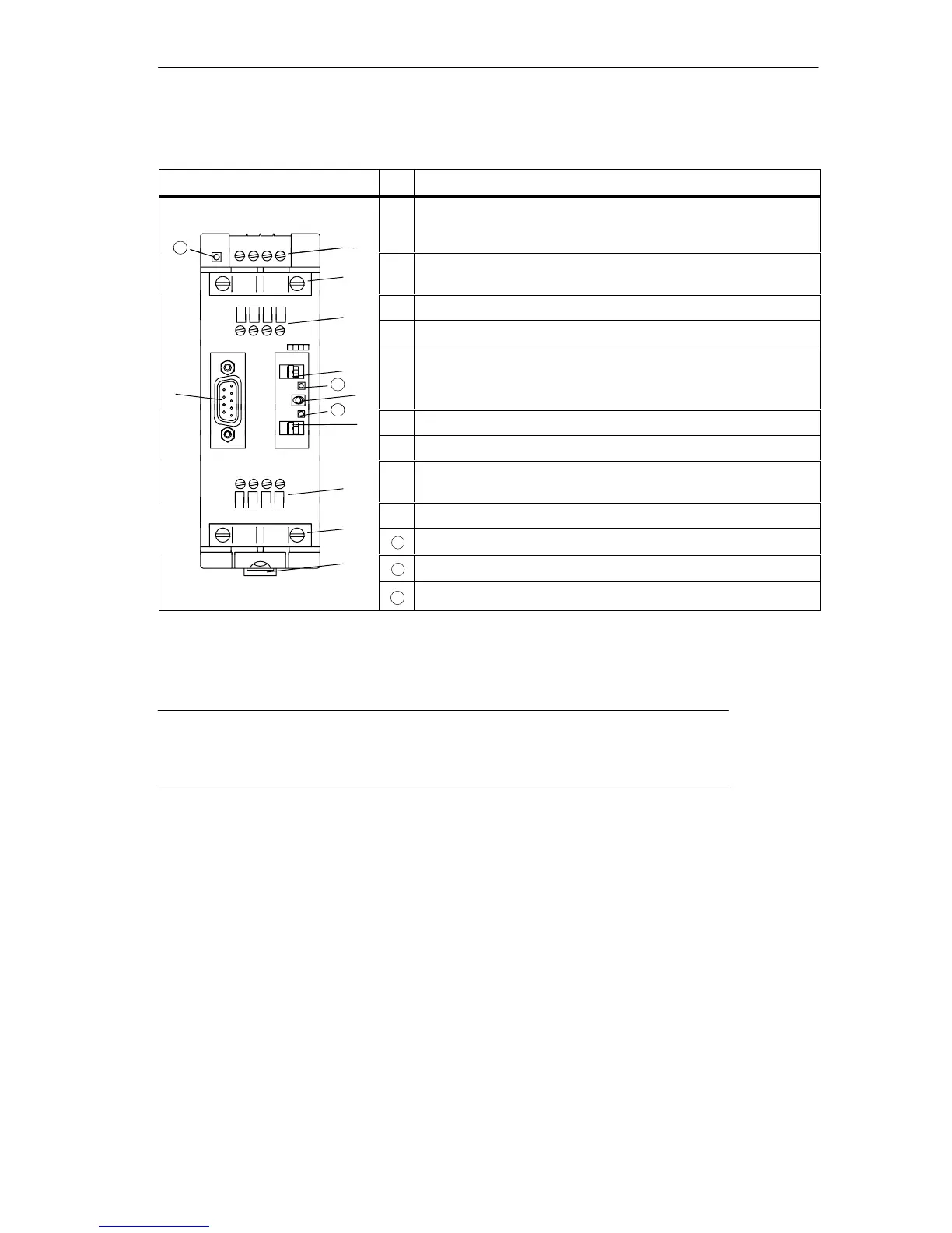
Table 5-1 Description and Functions of the RS-485 Repeater
Layout of the Repeater
No. Function
DC
24 V
L+ M PE M 5.2
À
10
À Terminal for connecting the power supply of the RS 485
repeater (pin “M5.2” is the reference ground if you want to
measure the voltage between terminals “A2” and “B2”).
24 V
Á
10
Á Shield clamp for strain relief and grounding the LAN cable of
bus segment 1 or bus segment 2
Â
 Terminal for the LAN cable of bus segment 1
A1 B1 A1 B1
à Terminating resistor for bus segment 1 )
1
Ã
Ä
È
A1 B1 A1 B1
PG
11
OFF
ON
DP1
Ä Switch for OFF state
(= Disconnect bus segments 1 and 2, for example, during
commissioning)
Å
OP
DP2
12
Å Terminating resistor for bus segment 2 )
1
SIEMENS
ON
Æ Terminal for the LAN cable of bus segment 2
SIEMENS
RS 485-REPEATER
Æ
A2 B2 A2 B2
Ç Catch for mounting and removing the RS-485 repeater on a
standard rail
È Interface for PG/OP on bus segment 1
10
LED 24 V power supply
Ç
11
LED indicating bus activity on segment 1
12
LED indicating bus activity on segment 2
)
1
If the terminating resistor is activated, the right-hand bus attachment is disconnected (see
Figure 5-3) !
Note
Terminal M5.2 of the power supply (see Table 5-1, no. À) is used as the reference
ground for signal measurements if problems occur and must not be wired up.