EasyManuals Logo

Siemens SIMATIC NET PROFIBUS User Manual

Siemens SIMATIC NET PROFIBUS
490 pages
To Next Page IconTo Next Page
To Previous Page IconTo Previous Page
Page #171 background imageLoading...
Page #171 background image
Active Components for RS-485 Networks
5-5
PROFIBUS Networks SIMATIC NET
6GK1970-5CA20-0AA1 Release 2 05/2000
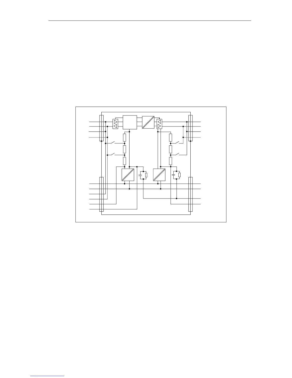
Block Diagram
Figure 5-1 shows the block diagram of the RS-485 repeater:
S Bus segment 1 and bus segment 2 are electrically isolated.
S Bus segment 2 and the PG/OP connector are electrically isolated.
S Signals are amplified:
– between bus segment 1 and bus segment 2
– between the PG/OP connector and bus segment 2
5V
24 V
Segment 2
A2
B2
A2
B2
Segment 1
A1
B1
A1
B1
PG/OP
socket
L+ (24 V)
M
A1
B1
5 V
M5 V
L+ (24 V)
M
PE
M 5.2
Logic
5V
24 V
1M1M
Figure 5-1 Block Diagram of the RS-485 Repeater

Table of Contents

Questions and Answers:

Question and Answer IconNeed help?

Do you have a question about the Siemens SIMATIC NET PROFIBUS and is the answer not in the manual?

Siemens SIMATIC NET PROFIBUS Specifications

General IconGeneral
BrandSiemens
ModelSIMATIC NET PROFIBUS
CategoryNetwork Hardware
LanguageEnglish

Related product manuals